


14
For example, the PS1 Vo
set,PS1
=5V, the PS2 Vo
set,PS2
=3.3V, R1 is calculated as follows:
KKR 303.1020*
32.1
]32.1)3.13.3[(
1 =
−−
=
Ω
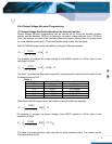
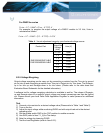
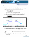
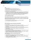
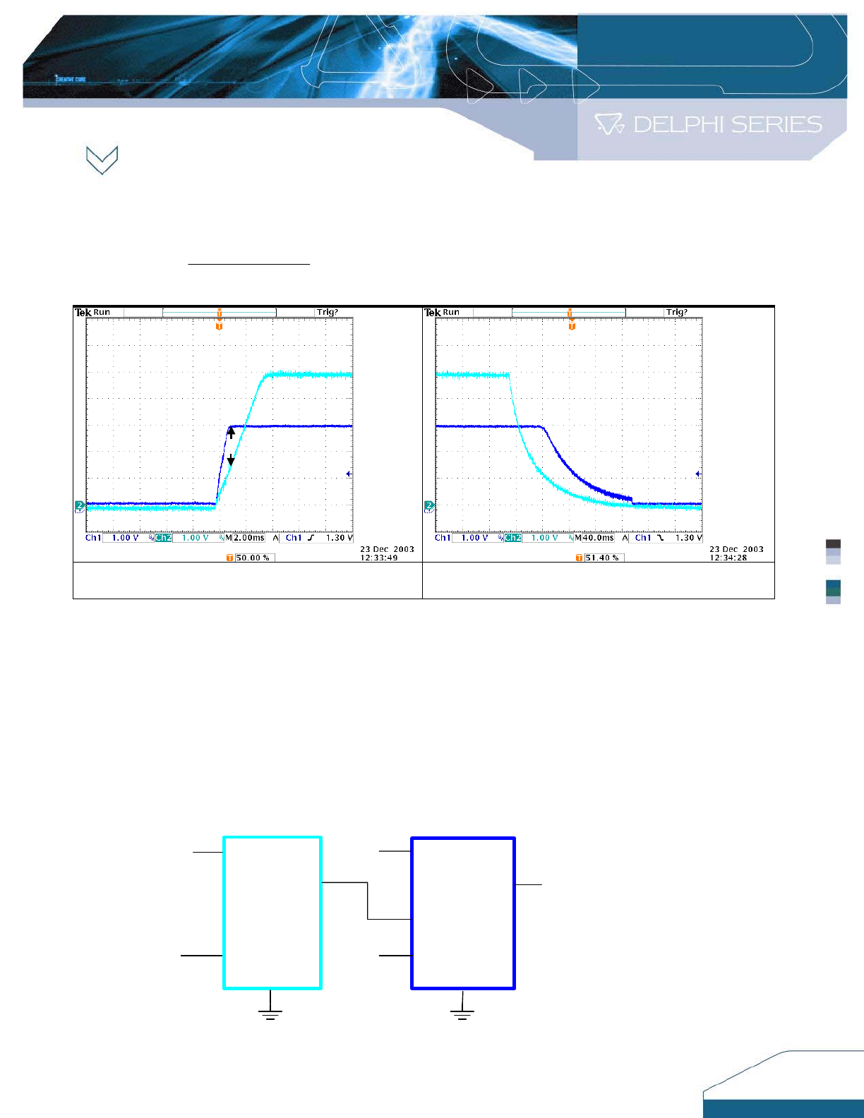
Figure 9. Ratio–metric tracking Power up Figure 10. Ratio–metric tracking Power down
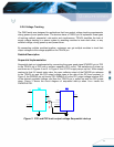
Simultaneous Implementation
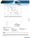
Similar to the ratio-metric implementation, simultaneous tracking is implemented by using a voltage
divider on the TRACK pin. The objective is to minimize the voltage difference between the power
supply outputs during power up and down. The waveforms of power up and down are showed in
Figures 13 and 14.
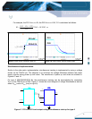
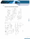
For type A (DNXXX0A0XXXX A), the simultaneous tracking can be accomplished by connecting
Vo
PS1
to the TRACK pin of PS2. Figure 11 shows the circuit diagram of voltage Simultaneous start-up
when Vo
PS2
tracks Vo
PS1
(only for type A).
TRACK
Vo
PS1
PS2
Vo
PS2
PS1
Vin
Vin
ENABLE
ENABLE
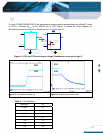
Figure 11. PS1 and PS2 track output voltage Simultaneous start-up for type A
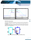
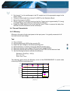
PS1=5
V
PS2=3.3V
PS1
PS2
-△V=1.3V