


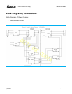

Switch Mode Power Supply DRP024V060W1BA
13/13 Rev: 00,
1/10/2011
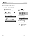
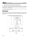
Parallel Operation:
When 2 Power Supplies are connected in parallel, they can share the load if the following steps are
taken.
Step 1:
Measure the output voltages at no load from A1 to Ground i.e. VA1 to Ground of PSU1 and VA2 to
Ground of PSU2. If the voltages are not the same, follow Step 2. If they are the same, skip to Step
3.
Step 2:
Adjust the output voltages, with the help of VR on the Power Supply front panel market as ADJUST,
to the same level. For e.g. if PSU1 is measuring 24.15Vdc and PSU2 is measuring 24.25Vdc, adjust
the output voltage of one to be the same as the other.
Step 3:
Connect the Power Supply to the end system load and measure the output voltages from A1 to
Ground i.e. VA1 to Ground of PSU1 and VA2 to Ground of PSU2. Ensure that the output voltages are
the same even after the 2 Power Supplies are connected to load. If not, adjust them with the VR
available on the front panel. A tolerance of +/-25mV would be acceptable.
Note:
1. If the output voltage of any Power Supply is higher, it will take the initial load and share the
maximum load.
2. If the output voltages are the same, then an equal load current sharing between the 2 Power
Supplies can be achieved.
3. The ORing diode must be of an appropriate rating. The rating must be at least 4 times of the
output load current and at least reverse voltage rating of 20Vrr.
4. The use of a heat sink is advised to ensure the ORing Diode does not overheat.
5. Recommended Redundancy Module: DRR-20A