


LCP-10G3A4EDR
DELTA ELECTRONICS, INC.
11 Revision: 0B
2008/9/5
www.deltaww.com
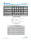
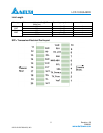
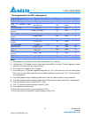
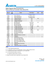
Timing parameters for SFP+ management
Parameter Symbol Min. Max. Unit Note
TX_DISABLE Assert time t_off 10 µsec 1
TX_DISABLE Negate time t_on 2 msec 2
Time to initialize 2-wire
interfase
t_2w_start_up 300 msec 3
Time to initialize t_start_up 300 msec 4
Time to initialize cooled
module
t_start_up_cooled 90 sec 4
Time to Power Up to Level 2 t_power_level2 300 msec 5
Time to Power Down from
Level 2
T_power_down 300 msec 6
TX_Fault assert TX_Fault_on 1 msec 7
TX_Fault assert for cooled
module
TX_Fault_on 50 msec 7
TX_Fault Reset t_reset 10 µsec 8
Module Reset t_module_reset TBD msec TBD
RS0, RS1 rate select timing
for FC
t_RS0_FC,
RS1_FC
500 µsec 9
RS0, RS1 rate select timing
non FC
t_RS0, t_RS1 10 msec 9
RX_LOS assert delay t_los_on 100 µsec 10
RX_LOS negate delay t_los_off 100 µsec 11
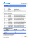
Notes:
1) Rising edge of TX_Disable to fall of output signal below 10% of nominal.
2)
Falling edge of TX_Disable to rise of output signal above 90% of nominal. This only applies in normal
operation, not during start up or fault recovery.
3)
From power on or negation of TX_Disable.
4)
From power on or TX_Disable negated during power up, or TX_Fault recovery, until non-cooled power
level 1 part (or non-cooled power level 2 part already enabled at power level 2 for TX_Fault recovery)
is fully operational.
5) From falling edge of stop bit enabling power level 2 until non-cooled module is fully operational.
6) From falling edge of stop bit disabling power level 2 until module is within power level 1 requirements.
7) From Occurrence of fault to assertion of TX_Fault.
8) Time TX_Disable must be held High to reset TX_Fault.
9) From assertion till stable output.
10) From Occurrence of loss of signal to assertion of LOS
11) From Occurrence of presence of signal to negation of RX_LOS.