


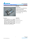

LCP-10G3A4EDR
DELTA ELECTRONICS, INC.
14 Revision: 0B
2008/9/5
www.deltaww.com
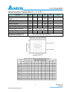
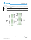
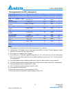
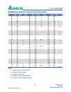
Digital Diagnostic Monitoring Interface
Alarm and Warning Thresholds (2-Wire Address A2h)
Address
#
Bytes
Name Value (Dec.) Unit Note
00-01 2 Temp High Alarm
85 degree Celsius
02-03 2 Temp Low Alarm
-10 degree Celsius
04-05 2 Temp High Warning
80 degree Celsius
06-07 2 Temp Low Warning
-5 degree Celsius
1
08-09 2 Voltage High Alarm
3.6V
10-11 2 Voltage Low Alarm
3.0V
12-13 2 Voltage High Warning
3.5V
14-15 2 Voltage Low Warning
3.1V
Volt
16-17 2 Bias High Alarm
Iop+10 mA
18-19 2 Bias Low Alarm
Iop-5 mA
20-21 2 Bias High Warning
Iop+7 mA
22-23 2 Bias Low Warning
Iop-3 mA
mA 2
24-25 2 TX Power High Alarm
P +3dB
26-27 2 TX Power Low Alarm
P-3dB
28-29 2 TX Power High Warning
P +2dB
30-31 2 TX Power Low Warning
P-2dB
dBm 3
32-33 2 RX Power High Alarm
0dBm
34-35 2 RX Power Low Alarm
-13.1dBm
36-37 2 RX Power High Warning
-1dBm
38-39 2 RX Power Low Warning
-11.1dBm
dBm 4
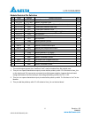
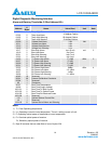
40-45 16 Reversed
56-91 36 External Calibration Constants
92-94 3 Reversed
95 1 Checksum 5
96-97 2 Real Time Temperature
98-99 2 Real Time Supply Voltage
100-101 2 Real Time Tx Bias Current
102-103 2 Real Time Tx Optical Power
104-105 2 Real Time Rx Received Power
106-109 4 Reserved
110 1 Optional Status/ Control Bits
111 1 Reserved
112-119 8 Optional Set of Alarm and Warning
Notes:
1) T
C
: Case Operating temperature
2) I
OP
: Operating current at room temperature. The min. setting current is 0 mA.
3) P: Operating optical power of transmitter at room temperature.
4) P
0
: Overload optical power of receiver
P
S
: Sensitivity optical power of receiver
5) Byte 95 contains the low order 8bits of sum of bytes 0-94