


DS_Q48DR1R533_03152007
6
ELECTRICAL CHARACTERISTICS CURVES
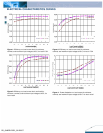
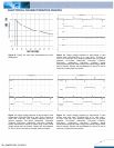
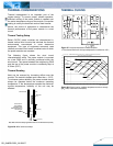
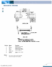
Figure 9: Typical full load input characteristics at room
temperature
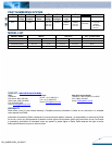
Figure 10: Output voltage response to step-change in load
current Iout2 (75%-50%-75% of Io, max; di/dt = 0.1A/µs) at
Iout1=7.5A. Load ca
p
: 10µF, tantalum capacitor and 1µF ceramic
capacitor. Ch1=Vout2 (100mV/div), Ch2=Iout2 (7.5A/div),
Ch3=Vout1 (100mV/div), Ch4=Iout1 (7.5A/div) Scope
measurement should be made using a BNC cable (length shorter
than 20 inches). Position the load between 51 mm to 76 mm (2
inches to 3 inches) from the module.
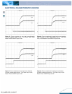
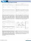
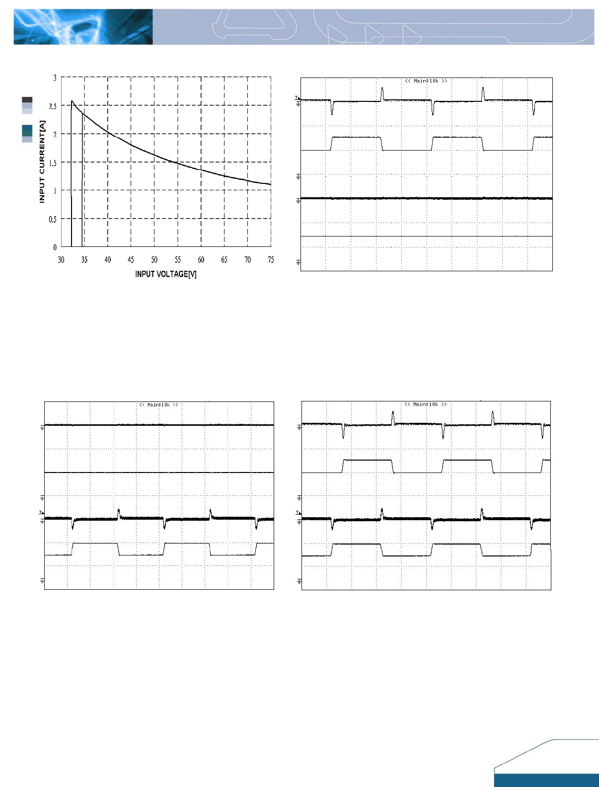
Figure 11: Output voltage response to step-change in load
current Iout1 (75%-50%-75% of Io, max; di/dt = 0.1A/µs) at
Iout2=7.5A. Load cap: 10µF, tantalum capacitor and 1µF
ceramic capacitor. Ch1=Vout2 (100mV/div), Ch2=Iout2
(7.5A/div), Ch3=Vout1 (100mV/div), Ch4=Iout1 (7.5A/div)
Scope measurement should be made using a BNC cable
(length shorter than 20 inches). Position the load between
51 mm to 76 mm (2 inches to 3 inches) from the module.
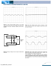
Figure 12: Output voltage response to step-change in load
current Iout2 and Iout1 (75%-50%-75% of Io, max; di/dt =
0.1A/µs). Load cap: 10µF, tantalum capacitor and 1µF ceramic
capacitor. Ch1=Vout2 (100mV/div), Ch2=Iout2 (7.5A/div),
Ch3=Vout1 (100mV/div), Ch4=Iout1 (7.5A/div) Scope
measurement should be made using a BNC cable (length shorter
than 20 inches). Position the load between 51 mm to 76 mm (2
inches to 3 inches) from the module.
Ch4
Ch3
Ch2
Ch1
Ch4
Ch3
Ch2
Ch1
Ch4
Ch3
Ch2
Ch1