


SFBD-1250B4Q1R
DELTA ELECTRONICS, INC.
3 Revision: S0
04/12/2007
www.deltaww.com
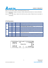
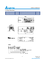
Note (5). Transmitter eye mask definition
4. Specification of Receiver
Parameter Symbol Min. Typ. Max. Unit Note
Input Optical Wavelength
λ
IN
1260 1310 1360 nm PIN-PD
Receiver Sensitivity P
IN
-23
dBm Note (1)
Input Saturation Power (Overload) P
SAT
-3 dBm
Signal Detect -Assert Power P
A
-24 dBm
Signal Detect -Deassert Power P
D
-44 dBm Note (2)
Signal Detect Hysteresis P
A
-P
D
0.5 2 5 dB
Data Output Rise/Fall time t
r
/t
f
260 ps Note (3)
Optical Receiver Reflectance -12 dB Note (4)
1550 to 1560nm -33 dB
Optical Isolation
from External
Source
1640 to 1665nm -33 dB
Note (1). Measured with Light source 1490nm, ER=9dB; BER =<10
-12
@PRBS=2
7
-1 NRZ
Note (2). When SD deasserted, the data output is Low-level (fixed)
Note (3). These are 20%~80% values.
Note (4). Measured at wavelength of 1310nm.
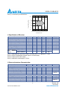
5. Electrical Interface Characteristics
Parameter Symbol Min. Typ. Max. Unit Note
Transmitter
Total Supply Current I
CC
A mA Note (1)
Differential line input Impedance R
IN
90 100 110 Ohm
Differential Data Input Swing VDT 400 1600 mV
p-p
Note (2)
Transmitter Disable Input-High V
DISH
2 V
CC
V
Transmitter Disable Input-Low V
DISL
0 0.8 V
LVTTL
Receiver
Total Supply Current I
CC
B mA Note (1)
Differential Data Output Swing VDR 400 800 1200 mV
p-p
Note (2)
Signal Detect Output Voltage-High V
LOSH
2 Vcc+0.3 V
Signal Detect Output Voltage-Low V
LOSL
0 0.8 V
Note (3)
1
0
X1 X2
1-X2
1-X1
1+Y3
1
1-Y1
0.5
Y1
0
-Y2
N
ormalized Time
N
ormalized Amplitude