


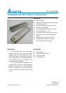


TSP-10G3A1EER
DELTA ELECTRONICS, INC.
7 Revision: S3
04/10/2007
www.deltaww.com
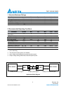
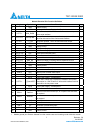
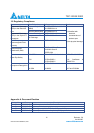
Module Electrical Pin Function Definition
Pin Logic Symbol Name/Description Note
1 GND Module Ground [1]
2 VEE5 Optional -5.2V Power Supply --Not Required
3 LVTTL-I Mod_DeSel
Module De-select; When held low allows module to respond to
2-wire serial interface
4 LVTTL-O Interrupt Bar
Interrupt Bar; Indicates presence of an important condition
which can be read over the 2-wire serial interface
[2]
5 LVTTL-I TX_DIS Transmitter Disable; Turns off transmitter laser output
6 VCC5 +5V Power Supply
7 GND Module Ground [1]
8 VCC3 +3.3V Power Supply
9 VCC3 +3.3V Power Supply
10 LVTTL-I/O SCL 2-Wire Serial Interface Clock [2]
11 LVTTL-I/O SDA 2-Wire Serial Interface Data Line [2]
12 LVTTL-O Mod_Abs Indicates Module is not present. Grounded in the Module [2]
13 LVTTL-O Mod_NR Module Not Ready; Indicating Module Operational Fault [2]
14 LVTTL-O RX_LOS Receiver Loss Of Signal Indicator [2]
15 GND Module Ground [1]
16 GND Module Ground [1]
17 CML-O RD- Receiver Inverted Data Output
18 CML-O RD+ Receiver Non-Inverted Data Output
19 GND Module Ground [1]
20 VCC2 +1.8V Power Supply --Not Required
21 LVTTL-I P_Down/RST
Power down; When high, requires the module to limit power
consumption to 1.5W or below. 2-Wire serial interface must be
functional in the low power mode.
22 VCC2 +1.8V Power Supply --Not Required
23 GND Module Ground [1]
24 PECL-I RefCLK-
Reference Clock Non-Inverted Input, AC coupled on the host board,
Not required
25 PECL-I RefCLK+
Reference Clock Inverted Input, AC coupled on the host board,
Not required
26 GND Module Ground [1]
27 GND Module Ground [1]
28 CML-I TD- Transmitter Inverted Data Input
29 CML-I TD+ Transmitter Non-Inverted Data Input
30 GND Module Ground [1]
Notes:
1. Module ground pins Gnd are isolated from the module case and chassis ground within the module.