


TSP-10G3A1EER
DELTA ELECTRONICS, INC.
9 Revision: S3
04/10/2007
www.deltaww.com
5 MOD_ABS
Mod_ABS is pulled up to Host_Vcc on the host board and grounded in the XFP module. Mod_ABS is then asserted
“
High
”
when the XFP module is physically absent from a host slot.
6 RX_LOS
The RX_LOS when High indicates insuf.cient optical power for reliable signal reception. The RX_LOS pin is an open
collector output and must be pulled up to Host_Vcc on the host board.
7 P_DOWN/RST
This is a multifunction pin for module Power Down and Reset. The P_Down/RST pin must be pulled up to VCC3 in the
XFP module.
7.1 POWER DOWN FUNCTION
The P_Down pin, when held High by the host, places the module in the standby (Low Power) mode with a maximum
power dissipation of 1.5W.
This protects hosts which are not capable of cooling higher power modules which may be accidentally inserted.
The module
’
s 2-wire serial interface and all laser safety functions must be fully functional in this low power mode.
During P_Down, the module shall still support the completion of reset Interrupt, as well as maintain functionality of the
variable power supply as described in XFP MSA Revision 3.1 section 5.7.
7.2 RESET FUNCTION
The negative edge of P_Down/RST signal initiates a complete module reset.
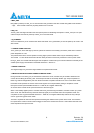
7.3 MODULE BEHAVIOR DURING POWER DOWN AND RESET
During execution of a reset (t_init) or while held in Power Down mode, a module may be unable to determine the
correct value for Mod_NR and RX_LOS. These outputs as well as all interrupt related .ags, except completion of
Reset .ag, shall be disregarded by the host. When the module completes a Reset and is not in Power Down mode,
the module must represent the correct value of both signals on its outputs before posting a completion of reset
interrupt to the host (see XFP MSA Revision 3.1 Table 39, bit 0 register address 84).
At no time shall a module cause spurious assertion of the Interrupt pin.
When a host initially applies power to a module with the P_Down/RST signal asserted, a module comes up in power
down mode. The module shall only assert the Interrupt signal pin to informthe host it has completed a reset. The
completion of reset .ag (see XFP MSA Revision 3.1 Table 39, bit 0 register address 84) shall be the only interrupt
source .ag set during power down mode.
The host is expected to clear this interrupt before releasing the module from the power down mode. The transition
from power down mode to normal mode will trigger a reset of the module and result in a 2nd module reset and a 2nd
reset completion interrupt to the host