


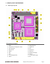
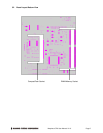
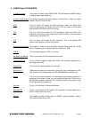

4. JUMPER and I/O HEADERS
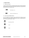
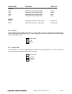
J1 CMOS Jumper This jumper is used to clear CMOS RAM. This will restore the BIOS settings
to factory default upon power up.
J5 Serial Port2 Jumper This jumper is used to set serial protocol for Serial Port 2. Users can select
between RS-232, 422, and 485.
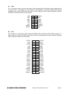
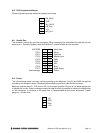
VGA This is a 16-pin I/O header for VGA connection. Users can obtain VGA
output by connecting the female end of the VGA connector to this header
and connecting the other end to the monitor.
LCD This is a 40-pin Box header for LCD connection. Users can obtain LCD
output by connecting the box header end of the LCD cable to this connector
and the other end to the LCD.
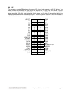
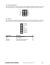
IDE This is a 44-pin I/O header for IDE connection. This is the primary IDE
channel and supports up to two IDE devices.
Compact Flash Socket This socket is used to mount and boot compact flash device as an IDE
device. Supports type I/II compact flash and sizes up to 1GB.
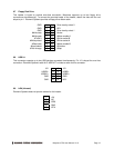
USB 0-1 This connector supports 2 USB 1.1 devices.
Keyboard and Mouse This is a connector for PS/2 keyboard and mouse.
Floppy Disk Drive This is a 20-pin header for floppy disk drives. The connector supports up to
two floppy disk drives.
Parallel Port This is a 20-pin header parallel port connector.
Serial Port 1-2 These two are serial port connectors. Serial port one is designated as RS-
232. Serial port 2 is configurable to be RS-232/422/485 by jumpering J5.
Power This is a 4-pin power connector. It is the external input power connector for
powering up the board. Power may be supplied through the PC104 bus or
through this connector. Morpheus only requires power to be supplied to the
5V and ground pins to power up.
Ethernet This is a 10/100 Base-Tx Ethernet connector.
Ethernet LED This is a 4-pin Ethernet LED header. This connector is used to power up an
LED to indicate Ethernet activity.
Utilities This header provides utilities such as RESET, external speaker, external
SMI, and hark disk activity LED.
Morpheus CPU User Manual V1.01 Page 6