


Prometheus-LC CPU User Manual V1.0 Page 31
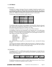
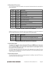
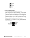
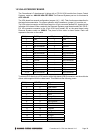
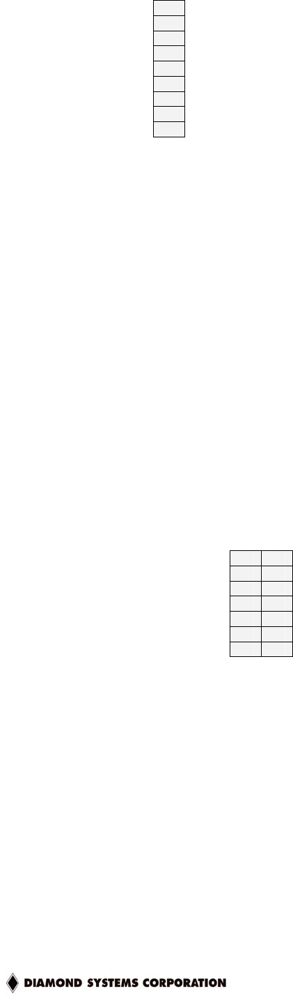
1 Power Switch
2 Power Input
3 +12V In
4 +5V In
5 Ground
6 Power Input
7 Shutdown
8 +5V In
9 Ground
J13 pinout (user connection)
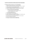
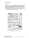
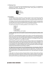
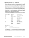
12.6 Speaker and Miscellaneous Connector
J3 is used for optional connection of an auxiliary speaker or control switches.
The panel board contains a miniature speaker which is enabled by default. To enable this
speaker, install a jumper across pins 11 and 13 of J3 (default setting). If a different speaker is
desired, or if no speaker is desired, remove the jumper.
To connect an auxiliary speaker, connect the speaker across pins 7-8 (for a speaker with a 2-pin
2-position housing) or across pins 7-13 (for a speaker with a 2-pin 4-position housing when the
two wires are on the two end positions of the housing).
External momentary switches may be connected to J3 to control power or reset. For power,
connect the switch between pins 1 and 2 of J3. For reset, connect the switch between pins 3 and
4. Each switch operates by connecting the selected control signal to ground.
To lock out the keyboard and mouse ports on the panel board, install a jumper across pins 5-6.
To disable the ATX power function, connect a jumper across pins 12 and 14 on J3.
An auxiliary switched +5V pin is provided on J3 for customer application. In addition the
unswitched power may be used on this header to power a panel light or other customer circuit,
with the current limited to 1A.
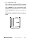
Ground 1 2 Power Switch
Ground 3 4 Reset Switch
Ground 5 6 Keyboard/Mouse Lockout
+5VDC Unswitched 7 8 Speaker
+5VDC Switched 9 10 N/C
Internal Speaker 11 12 Ground
Speaker 13 14 ATX Disable
J3 Pinout