


Prometheus-LC CPU User Manual V1.0 Page 8
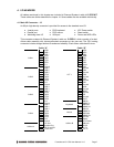
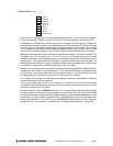
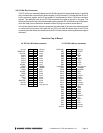
Notes on J3 Signals
COM1 – COM4
The signals on these pins are RS-232 level signals and may be
connected directly to RS-232 devices. The pinout of these signals is
designed to allow a 9-pin male IDC connector to be crimped onto the
corresponding ribbon cable wires to provide the correct pinout for a PC
serial port connector (DTE).
LPT1
The signals on these pins comprise a standard PC parallel port. The
pinout of these signals is designed to allow a 25-pin female IDC
connector to be crimped onto the corresponding ribbon cable wires to
provide the correct pinout for a PC parallel port connector.
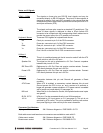
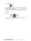
Keyboard, Mouse
These are PS/2 signals for keyboard and mouse.
Clk Clock pin; connects to pin 5 of the PS/2 connector.
V- Power pin; connects to pin 3 of the PS/2 connector.
Data Data pin; connects to pin 1 of the PS/2 connector.
V+ Power pin; connects to pin 4 of the PS/2 connector.
Pins 2 and 6 on the Mini-Din-6 PS/2 connectors are unused.
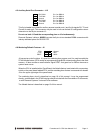
Utilities A
+5V Out This pin is a switched power pin that is turned on and off with the ATX
power switch or with the +5V input.
Speaker Out The signal on this pin is referenced to +5V Out. Connect a speaker
between this pin and +5V Out.
IDE Drive LED Referenced to +5V Out. Does not require a series resistor. Connect
LED directly between this pin and +5V Out.
Power LED Referenced to +5V Out. Does not require a series resistor. Connect
LED directly between this pin and +5V Out.
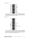
Utilities B
Reset- Connection between this pin and Ground will generate a Reset
condition.
ATX Power When ATX is enabled, a momentary contact between this pin and
Ground causes the CPU to turn on, and a contact of 4 seconds or
longer will generate a power shutdown. ATX power control is enabled
with a jumper on jumper block J10 (see page 14).
KB Lock When this pin is connected to Ground, the keyboard and mouse inputs
are ignored.
IR RX, IR TX IrDA pins. Can be connected directly to an IrDA transceiver.
+5V In Connected to +5V input power on J11 (see page 9). This pin is not
switched by ATX control. This pin is provided for auxiliary use such as
front panel lighting or other circuitry at the user’s discretion.
Connector Part Numbers
J3 plug on CPU board: 3M / Robinson Nugent no. P50E-080P1-S1-TG
Both cable-mount and board-mount connectors are available to mate with J3:
Cable-mount socket: 3M / Robinson Nugent no. P50E-080S-TG
Board-mount socket: 3M / Robinson Nugent no. P50-080S-R1-TG