


Prometheus-LC CPU User Manual V1.0 Page 30
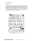
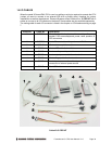
12.5 Panel Board Power Connections
Prometheus-LC requires only +5V for operation. The panel boad is simply a connector board and
requires no power. Make sure that the power supply used has enough current capacity to drive
your system. The Prometheus-LC CPU requires up to 1.1A. If you have a disk drive or other
modules connected, you need additional power. In particular, many disk drives need extra current
during startup. If your system fails to boot properly, or if disk accesses do not work properly, the
first thing to check is the power supply voltage level. Many boot-up problems are caused simply
by insufficient voltage due to excess current draw on the +5V supply.
The panel board has two external input power connectors, J11 and J13, to satisfy a variety of
input power scenarios.
J11 is a circular jack with a 2.5mm post. This connector is intended for direct 5VDC +/-5% input
from the Diamond Systems PS-5VUS-01 wall adapter or an equivalent supply. The polarity for
the power connector is tip = +5V, ring = Ground.
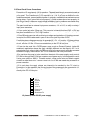
J13 is a DB9 male connector with multiple input voltages and applications. If a latching connector
is required, the DB9 can be used in place of the circular jack to provide +5VDC.
If multiple system voltages are required, for example +5V, -5V, +12V, and/or -12V, these voltages
can be supplied through J13 as well. The +5V and +12V are controlled by the CPU’s ATX power
circuit, while the -5V and -12V are connected directly to the PC/104 bus pins.
J13 can also be used with a DC/DC power supply, such as Diamond Systems’ Jupiter-MM
modules, in applications where the supply voltage is different from the required +5V. In this
scenario, the input voltage is fed to the DB9 and routed to the power supply with cable connected
between the supply and connector J5 or J12 on the bottom side of the panel board.
J5 is used when the power is to be routed from the output of the power supply directly onto the
PC/104 bus through the PC/104 bus connectors on the power supply. In this application use the
2-wire power cable no. 698011. This cable contains a blue positive wire and a black negative
wire. Connect the blue wire to the + screw terminal on the JMM power supply input connector and
connect the black wire to the – terminal. Either J4 or J5 on the JMM board may be used for the
power connection.
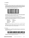
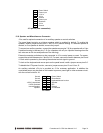
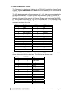
J12 is used when the supply voltages are intended to be switched by the ATX circuit on
Prometheus. In this application the input and output of the power supply are connected to J12.
The +5V and +12V are controlled by the ATX function, while the -5V and -12V are connected
directly to the PC/104 bus pins.
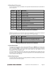
1 -12V In
2 -5V In
3 Ground
4 +5V In
5 +5V In
6 +12V In
7 Ground
8 Power Input
9 Ground
10 Shutdown/ATX
J12 pinout (to/from DC/DC power supply)