


Edgeport Installation Guide (90000403 Rev. D) – Page 2
Edgeport /1, Edgeport/2, Edgeport/4,
Edgeport/8, Edgeport/8r, Edgeport/8rr
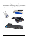
The Edgeport/2, Edgeport/4, Edgeport/8, Edgeport/8r, and Edgeport/8rr from Digi International are intelligent,
stackable expansion modules that connect to a PC or server running Windows 95, 98, SE, CE, Me, NT 4.0, 2000, or
Windows XP via the Universal Serial Bus (USB), providing high-speed serial connectivity. For more detailed
information as well as the latest manual and technical updates, visit www.digi.com/support.
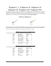
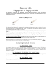
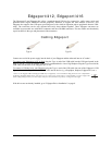
Cabling Edgeport
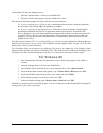
Type A Type B
Plug the Type A end of the USB cable into the USB port located in the back of your PC or into an available USB
port on a standard hub or into a Digi Hubport. Plug the Type B end of the USB cable into the back of the Edgeport.
If the drivers are not already installed, go to "Edgeport Driver Installation” on page 8.
Edgeport/8r RJ-45 Pin Assignments
Use the table below to find the RJ-45 pin assignments for your Edgeport/8r.
Signal Description DTE Use Pin #
RTS Request to Send Output 1
DSR Data Set Ready Input 2
DCD Data Carrier Detect Input 3
RXD Received Data Input 4
TXD Transmitted Data Output 5
SG Signal Ground Reference 6
DTR Data Terminal Ready Output 7
CTS Clear to Send Input 8
Edgeport/8rr RJ-12 Pin Assignments
Use the table below to find the RJ-12 pin assignments for your Edgeport/8rr.
Signal Description DTE Use Pin #
RTS Request to Send Output 1
CGND Chassis Ground Reference 2
TXD Transmitted Data Output 3
RXD Received Data Input 4
GND Ground Reference 5
CTS Clear to Send Input 6