


Install Guide
Model: MIL-4711H 3
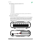
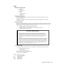
Figure 3.MIL-4711 (Rear View w/ the MIL-4310 Module)
Description of the LEDs
On the front panel of the MIL-4711H, there is one LED above each of the eight,
10BASE-T ports. If the port is in use, the LED will change to one of three colors to
indicate the following functions:
• Green indicates
link
present
• Red indicates that the port is partitioned
• Orange indicates that the port is receiving data
There are four LEDs located between the power plug and the DB-9 serial port on
the rear panel. The following gives the rear panel LEDs' function:
• Green LED in the upper-left corner is the system LED (SYS)
• Green LED in the lower-left corner is the power LED (PWR)
• Yellow LED in the upper-right corner is the network LED (NET)
• Red LED in the lower-right corner is the collision LED (COL)
Note:
The SYS and COL LEDs blink when the unit is operational.
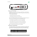
Description of Dip Switches
To the right of the DB-9 serial port (on the rear of the hub) are two DIP switches.
The switch to the left and closest to the DB-9 is Switch 2, and the switch to the
right is Switch 1. The following table gives the function of these DIP switches:
Switch 2 Switch 1 FUNCTION
Off (Down) Off (Down) Normal Mode (Telnet Disabled)
Off (Down) On (Up) Normal Mode (Telnet Enabled)
On (Up) On (Up) Monitor Mode, SNMP (Agent not Operational)
X X
16VAC
MIL-4300M
MIL-4310M
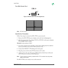
FT
LK
RX
CX