


6
I
DENTIFYING
E
XTERNAL
C
OMPONENTS
This section identifies all the major external components of
the DSS-5+. Both the front and rear panels are shown
followed by a description of each panel feature. The indicator
panel is described in detail in the next chapter.
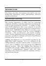
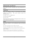
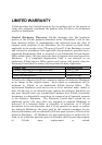
Front Panel
The figure below shows the front and rear panels of the DSS-
5+ .
DSS-5+ 10/100M Switch
LED Indicator Panel
Refer to the LED Indicator section for detailed
information about each of the hub’s LED indicators.
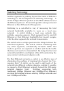
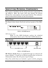
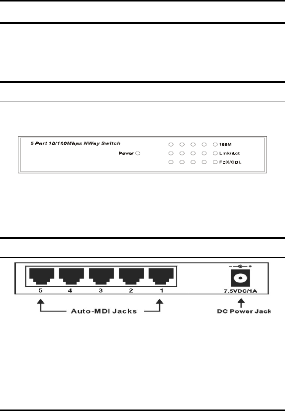
Rear Panel
DSS-5+ 10/100M Switch
DC Power Jack: Power is supplied through an external AC
power adapter. Check the technical specification section for
information about the AC power input voltage.
Since the switch does not include a power switch, plugging