


2
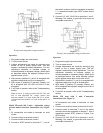
Figure 1
Wiring 2 units (adjustable voltage on unit #1)
Operation:
1. Plug power supply into octal socket.
2. Turn on power source.
3. Voltage adjustments are made by removing plug
button on top of power supply case. This will
expose a screwdriver slotted adjustment. Turn the
adjustment clockwise to increase voltage, or
counterclockwise to decrease voltage. When wired
as described above, the adjusted voltage will be
applied across unit #1.
4. With switch in position P1, unit #1 is energized with
adjusted voltage and unit #2 is de-energized.
5. With switch in position P2 (normally closed), unit
#2 is energized with 100 VDC and unit #1 is de-
energized.
6. If unit fails to operate, refer to the Troubleshooting
section.
Note: If unit #1 is energized with fixed 100 VDC, and
unit #2 with adjustable DC voltage, remove lead
between terminal 2 of octal socket and P2
b of switch.
Add lead between terminal 2 of octal socket and P1
b of
switch.
Model 250 used with 2 units – adjustable voltage
on both units.Connection Instructions (See Figure
2):
1. All connections are made to terminals on octal
socket.
2. Connect unit #1 to terminals 6 and 8.
3. Connect unit #2 to terminals 3 and 6.
4. Connect a SPDT switch to terminals 3, 7, and 8;
the switch common must be connected to terminal
7. A maintained-contact type SPDT switch should
be used.
5. Connect 115 VAC, 50-60 Hz to terminals 1 and 5.
Warning: The neutral or grounded side must be
connected to terminal 5.
Figure 2
Wiring 2 units (adjustable voltage on both units)
Operation:
1. Plug power supply into octal socket.
2. Turn on power source.
3. Voltage adjustments are made by removing plug
button on top of power supply case. This will
expose a screwdriver slotted adjustment. Turn the
adjustment clockwise to increase voltage, or
counterclockwise to decrease voltage. When wired
as described above, this same adjusted voltage
will be applied across both unit #1 and unit #2.
4. With switch in position P1, unit #1 is energized with
adjusted voltage and unit #2 is de-energized.
5. With switch in position P2 (normally closed), unit
#2 is energized with adjusted voltage and unit #1 is
de-ener-gized.
6. If unit fails to operate, refer to the Troubleshooting
section.
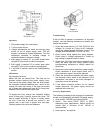
Model 250 used with 1 unit. Connection
Instructions (See Figure 3):
1. All connections are made to terminals on octal
socket.
2. Connect unit (clutch or brake) to terminals 6 and 8.
3. Connect switch to terminals 7 and 8; the switch
common should be connected to terminal 7. Use a
maintained contact SPDT (shown in Figure 3) or
SPST switch.
4. Connect 115 VAC, 50-60 Hz to terminals 1 and 5.
Warning: The neutral or grounded side must be
connected to terminal 5.