


3
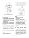
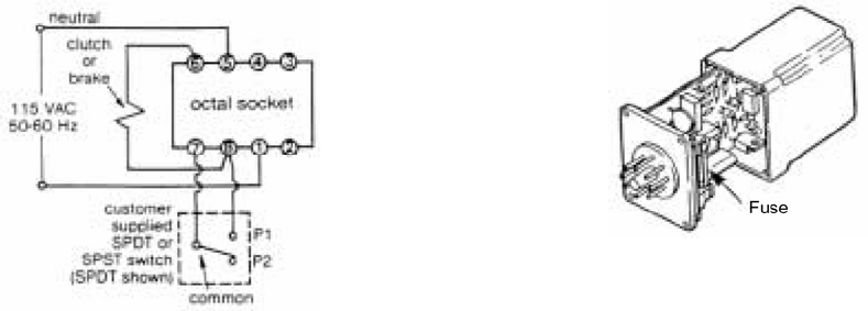
Figure 3
Wiring for 1 unit
Operation:
1. Plug power supply into octal socket.
2. Turn on power source.
3. Voltage adjustments are made by removing plug
button on top of power supply case. This will
expose a screwdriver slotted adjustment. Turn the
adjustment clockwise to increase voltage, or
counterclockwise to decrease voltage.
4. With switch in position P1 (or switch closed when
usingSPST) the clutch or brake is energized.
5. With switch in position P2 (or switch open when
usingSPST) the clutch or brake is de-energized.
6. If unit fails to operate, refer to the Troubleshooting
section.
Maintenance
Fuse location and access
Model 250 has an internal fuse. The fuse can be
checked without removing the power supply cover.
First remove the power supply from the octal socket.
An ohmmeter connected between pins 1 and 4 on the
module will read near infinity if the fuse has burned
out. If blown then replace with type 3AG 0.6 amp fuse.
Caution: Do not use slow-blow type fuse.
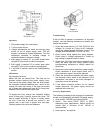
To replace the fuse, remove four fasteners holding
cover of base plug. Carefully remove the cover. The
fuse is located as shown in Figure 4. Visually check
the fuse. If the fuse is burned out, remove it, and
replace with a new fuse of proper size and type.
Carefully replace the cover and fasteners.
Figure 4
Fuse Location
Troubleshooting
If the unit fails to operate or operates in an improper
manner, use the following procedure to identify and
resolve the problem.
1. Check the power source (115 VAC, 50-60 Hz line
voltage). Is it turned on? Using an AC voltmeter,
check the voltage between terminals 1 and 5. The
voltage should be between 110 and 120 VAC.
2. Check actual wiring against the wiring diagram.
Check tosee if voltage adjustment is turned up
high enough to operate clutch or brake.
3. Check fuse. If the fuse is burned out, replace it with
oneof the same type and rating. Review entire
troubleshooting procedure to identify reason for
blown fuse.
4. Disconnect clutch and/or brake from power supply.
Check resistance of clutch and/or brake coils. If
coil is shorted or open it should be replaced.
5. Check the connections between the power supply
and theclutch and/or brake to be operated. If the
connections are loose or the wires damaged or
grounded, correct the problem.
6. If the above corrective actions do not restore
normal oper-ation, the power supply should be
replaced with a new one.
Accessory Requirements
The following accessories are required for installation,
but are not supplied with the Model 250 power supply.
1. Octal socket - DODGE part number 032401.
2. Switch - One switch (SPST, SPDT, or DPDT
depending upon applications). Switch should be
contact type. A minimum of 6A, 120VAC is
recommended.
3. Hook-up wire - as required.