


49
APPENDIX
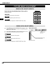
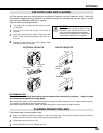
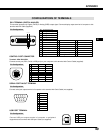
CONFIGURATIONS OF TERMINALS
Terminal : Mini DIN 8-PIN
Connect control port (PS/2, Serial or ADB port) on your computer to this terminal with Control Cable (supplied).
1
2
3
4
5
8 7 6
Pin Configuration
CONTROL PORT CONNECTOR
-----
CLK
DATA
GND
-----
-----
GND
-----
R X D
-----
-----
GND
RTS
T X D
GND
GND
-----
ADB
-----
GND
-----
-----
-----
GND
PS/2 Serial
ADB
1
2
3
4
5
6
7
8
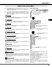
DVI-I TERMINAL (DIGITAL/ANALOG)
This terminal accepts only Digital (TMDS) or Analog (RGB) output signal. Connect display output terminal of computer to this
terminal with DVI cable (supplied).
1
9
17
2
10
18
3
11
19
4
12
20
5
13
21
6
14
22
7
15
23
8
16
24
C1
C2
C3
C5
C4
T.M.D.S. Data2–
No Connect
T.M.D.S. Data2+
No Connect
T.M.D.S. Data2 Shield
DDC Clock
DDC Data
Analog Vert. sync
1
5
2
4
3
6
7
8
Pin Configuration
T.M.D.S. Data1–
No Connect
T.M.D.S. Data1+
No Connect
T.M.D.S. Data1 Shield
+5V Power
Ground (for +5V)
Hot Plug Detect
9
13
10
12
11
14
15
16
T.M.D.S. Data0–
No Connect
T.M.D.S. Data0+
No Connect
T.M.D.S. Data0 Shield
T.M.D.S. Clock Shield
T.M.D.S. Clock+
T.M.D.S. Clock–
17
21
18
20
19
22
23
24
Analog Red Input
Analog Ground (R/G/B)
Analog Green Input
Analog Horiz. sync
Analog Blue Input
C1
C5
C2
C4
C3
-----
RxD
TxD
-----
Ground
-----
-----
-----
1
2
3
4
5
6
7
8
9 -----
12345
6789
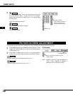
Connect serial port output terminal of computer to this terminal with Serial Cable (not supplied).
Pin Configuration
SERIAL PORT IN/OUT TERMINAL
E
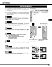
USB PORT TERMINAL
Pin Configuration
Connect USB port output terminal of computer or peripheral
equipment to this terminal with USB port Cable (not supplied).
2
34
1
Vcc
- Data
+ Data
Ground
1
2
3
4