


3
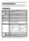
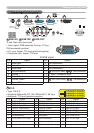
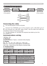
Connection to the ports
A
RGB IN1,
B
RGB IN2,
C
RGB OUT
D-sub 15pin mini shrink jack
• Video signal: RGB separate, Analog, 0.7Vp-p,
75Ω terminated (positive)
• H/V. sync. Signal: TTL level (positive/negative)
• Composite sync. Signal: TTL level
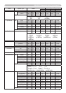
At RGB signal
Pin Signal Pin Signal
1
Video Red 9 (No connection)
2 Video Green 10 Ground
3 Video Blue 11 (No connection)
4
(No connection) 12
A
: SDA (DDC data),
B
/
C
: (No connection)
5 Ground 13 H. sync / Composite sync.
6 Ground Red 14 V. sync.
7
Ground Green 15
A
: SCL (DDC clock),
B
/
C
: (No connection)
8 Ground Blue
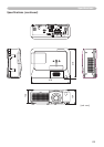
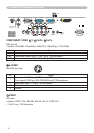
Connection to the ports
109876
54321
15
141312
11
24 25 26 27 28 29 30 23 22 21
20 19 18 17 16 15 14 13 12 11
8 7
10
9
6
5 4 3 2 1
VIDEO
CONTROL
AUDIO IN 1
AUDIO IN 2
REMOTE
CONTROL
(3.5Φ)
AUX I/O
DC 5V 0.5A
S-VIDEO
LAN
AUDIO
OUT
AC IN
I O
R L R L
AUDIO IN 3 AUDIO IN 4
RGB
OUT
RGB1 RGB2 M1-D
Y CB/PB
CR/PR
SD CARD
S
D
C
A
R
D
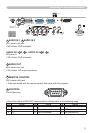
VIDEO
CONTROL
AUDIO IN 1
AUDIO IN 2
REMOTE
CONTROL
(3.5Φ)
S-VIDEO
LAN
AUDIO
OUT
AC IN
I O
R L R L
AUDIO IN 3 AUDIO IN 4
RGB
OUT
RGB1 RGB2 M1-D
Y CB/PB
CR/PR
A BC
D
D
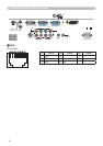
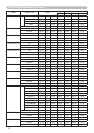
M1-D
• Type: T.M.D.S
• Amplitude differential: DC 150-1200mV/AC 1.56 Vp-p
• Amplitude: TTL level (positive/negative)
Pin Signal Pin Signal Pin Signal
1 T.M.D.S. Data2 + 11 T.M.D.S. Data1 + 21 T.M.D.S. Data0 +
2 T.M.D.S. Data2 - 12 T.M.D.S. Data1 - 22 T.M.D.S. Data0 -
3 T.M.D.S. Data2 Return 13 T.M.D.S. Data1 Return 23 T.M.D.S. Data0 Return
4 T.M.D.S. Clock Return 14 T.M.D.S. Clock +
24 USB +5V DC Input
5 (No connection) 15 T.M.D.S. Clock - 25 DDC & USB Return
6 V.Sync. 16 USB Data + 26 DDC Data (SDA)
7 (No connection) 17 USB Data -
27
DDC Clock (SCL)
8
Hot Plug Detect (+5V DC Output)
18 (No connection)
28 DDC +5V DC Input
9 (No connection) 19 (No connection)
29
(No connection)
10
(No connection) 20 (No connection)
30
(No connection)