


Silicon Image, Inc. iScan Pro User Manual
10
Color Space Selection
The iScan Pro can output video in one of two different color spaces. The first is the Red-Green-Blue
(RGB) color space that is commonly used for projectors, displays and monitors that are designed to
accept computer video output.
The second is Component Video, but is more accurately called YPbPr though you may hear it
referred to as Y-Pr-Pb, YUV, Y-Cr-Cb or Y/B-Y/R-Y (read “Y, B minus Y, R minus Y”). This color
space is commonly used for newer digital TV sets, displays and projectors that are designed for
use with Digital TV (DTV) tuners.
You will need to determine which color space is used by your progressively scanned display and
move the Color Space switch on the front panel of the iScan Pro to the appropriate position.
UP RGB
DOWN YPbPr
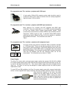
Typically, inputs on display devices that are labeled “Component Video”, “DTV” or “HDTV” are
YPbPr whereas inputs that are labeled “Computer” or “VGA” are RGB. Once set up, this switch
should not need to be changed unless you are changing display devices.
Synchronization Signals
All video devices require one or more synchronization signals that tell the device when to start a
new line and/or a new field. For YPbPr devices, this sync information is embedded in the Y signal.
For RGB devices, there are a variety of ways that this sync information can be conveyed and the
iScan Pro can support most of these. The iScan Pro generates separate H (horizontal) and V
(vertical) sync signals in addition to the RGB outputs. This results in a total of five signals
(RGB/HV). For many configurations, these five signals will be part of a single VGA-to-VGA output
cable and there will be no need to worry about the individual signals. For some devices you may
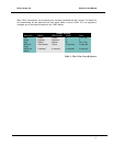
need to connect all five of these signals to individual BNC or possibly RCA type connectors. See
Table 1 below for more specific connection information.
Some display devices require that the two H and V sync signals be combined into a single
“composite sync” signal, resulting in a total of 4 signals (RGB/S). Devices requiring composite sync
typically accept the three video signals as well as the composite sync signal on BNC type
connectors.
Other devices require that the composite sync signal be further combined with the RGB Green
signal. This is referred to as “sync on green” and is typically connected to the device using 3 BNC
connectors, though 3 RCAs may also be used.
If your output device falls into either of these last two categories – composite sync or sync on green
– the iScan Pro will need to be internally configured to output the appropriate type of sync signal. To
do this you will need to follow the directions in Appendix A.