www.eaton.com
Network Shutdown Module V3 – User Manual - 34 003 934 XU / AE Page 15/65
3 Minimal configuration steps
3.1 Introduction
In this chapter we describe the basic and minimal configuration steps that must be performed before using the
Network Shutdown Module.
The other and optional configuration possibilities are described later
.
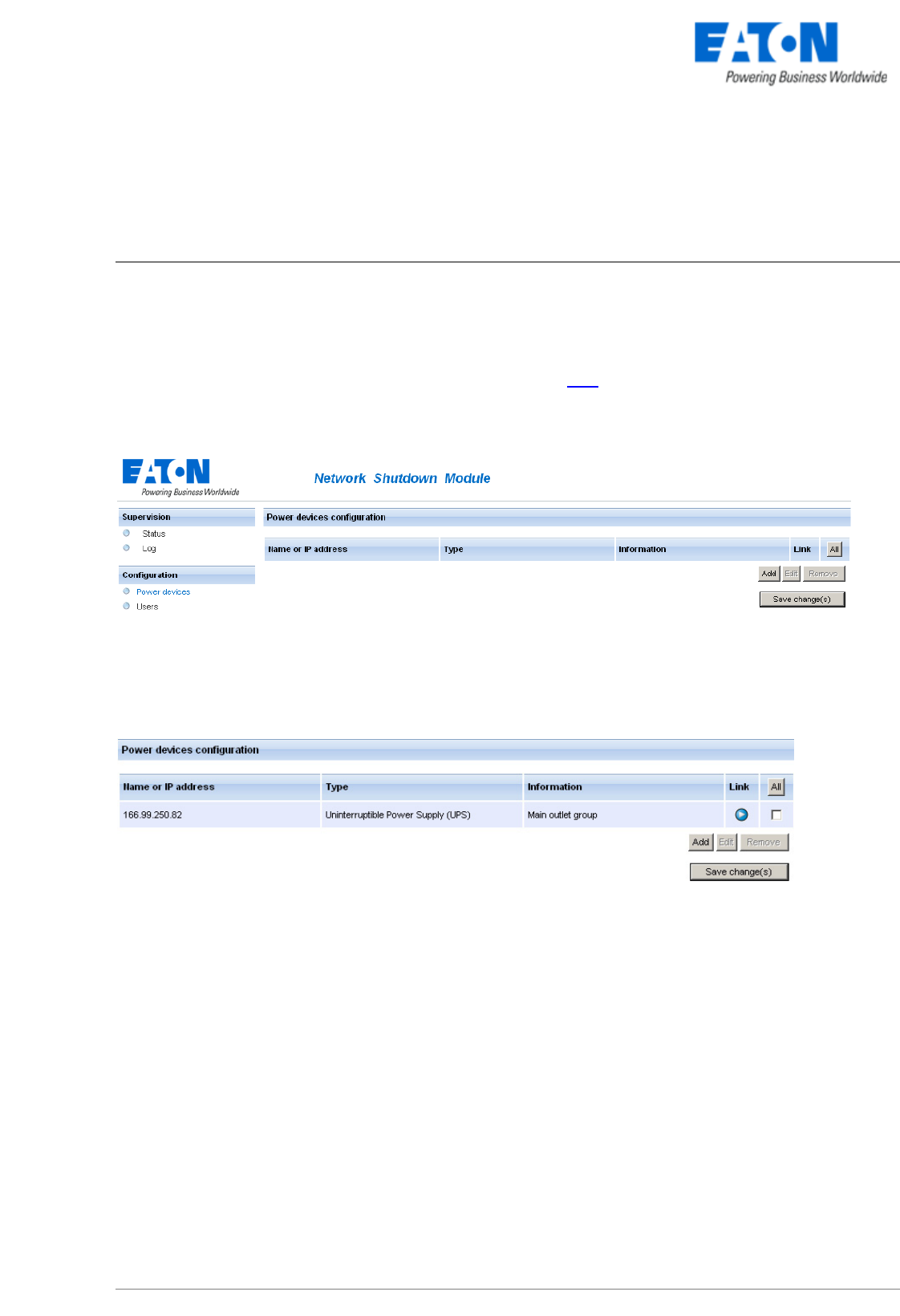
3.2 The IP address of the UPS that powers your server.
In the Configuration -> Power device screen, click on the Add button
Adding a power device
Then following screen appears:
> Enter the IP (or the host name) of the Network Management Card (or Proxy)
or use the following new function:
New: With the Quick Scan … button, available with version 3.10 and later, you can discover
in a few seconds the cards connected to the network and then select a card from the list.
Power device settings
From this screen, you can define the following parameters:
z Network Name or IP address of the Network Management Card / Proxy. This parameter must correspond
to the UPS that powers your machine.
z The UPS Outlet that powers the server
Powershare outlets and load shedding:
You have the possibility in this page to configure the electrical dependency between one of the UPS
switchable plugs and the server hosting Network Shutdown Module.
This function is useful for the servers that must be first shut down during the autonomy sequence.


