


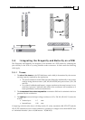
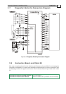

3.5 Integrating the Dragonfly and Butterfly on a PCB
The Dragonfly and Butterfly are designed to be mounted on a PCB, either by soldering the
pins directly to the PCB or by using suitable socket connectors. In both cases the following
rules apply:
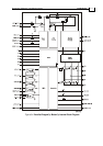
3.5.1 Traces
1. The size of the traces on the PCB (thickness and width) is determined by the current
carrying capacity required by the application.
The rated continuous current limit (Ic)of the Dragonfly and Butterfly is the current
used for sizing the motor traces (M1, M2, M3 and PE) and power traces (VP+, PR
and PE).
For control, feedbacks and Inputs/ outputs conductors the actual current is very
small but “generous” thickness and width of the conductors will contribute to a
better performance and lower interferences.
2. The traces should be as short as possible to minimize EMI and to minimize the heat
generated by the conductors.
3. The spacing between the high voltage conductors (VP+, PR, M1, M2, M3, VL) must be
at least:
Surface layer: 1.5 mm
Internal layer: 0.10 mm
Complying with the rules above will help satisfy UL safety standards, MIL-STD-275 and the
IPC-D-275 standard for non-coated conductors, operating at voltages lower than 100VDC and
at "unlimited altitudes" (above 10,000 meters – 30,000 feet).
Dragonfly/ Butterfly Installation Guide Installation
MAN-DRBUIG (Ver. 1.1)
3-4