


61
SECTION 2. INSTALLATION
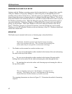
This section describes the cable connection, the Windows Plug and Play Setup, and the physical
mounting of the unit.
USB CONNECTION
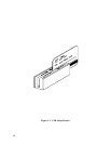
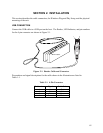
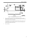
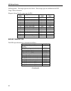
Connect the USB cable to a USB port on the host. The Reader, LED Indicator, and pin numbers
for the 4-pin connector are shown in Figure 2-1.
LED Indicator
14
Figure 2-1. Reader Cable and Connector
Pin numbers and signal descriptions for the cable shown in the illustration are listed in
Table 1-1.
Table 2-1. 4-Pin Connector
Pin Number Signal Cable Color
1 V
CC
Red
2 - Data White
3 +Data Green
4 Ground Black