5
Planning Your Hardware Components
5-13
Storage System Hardware
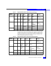
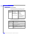
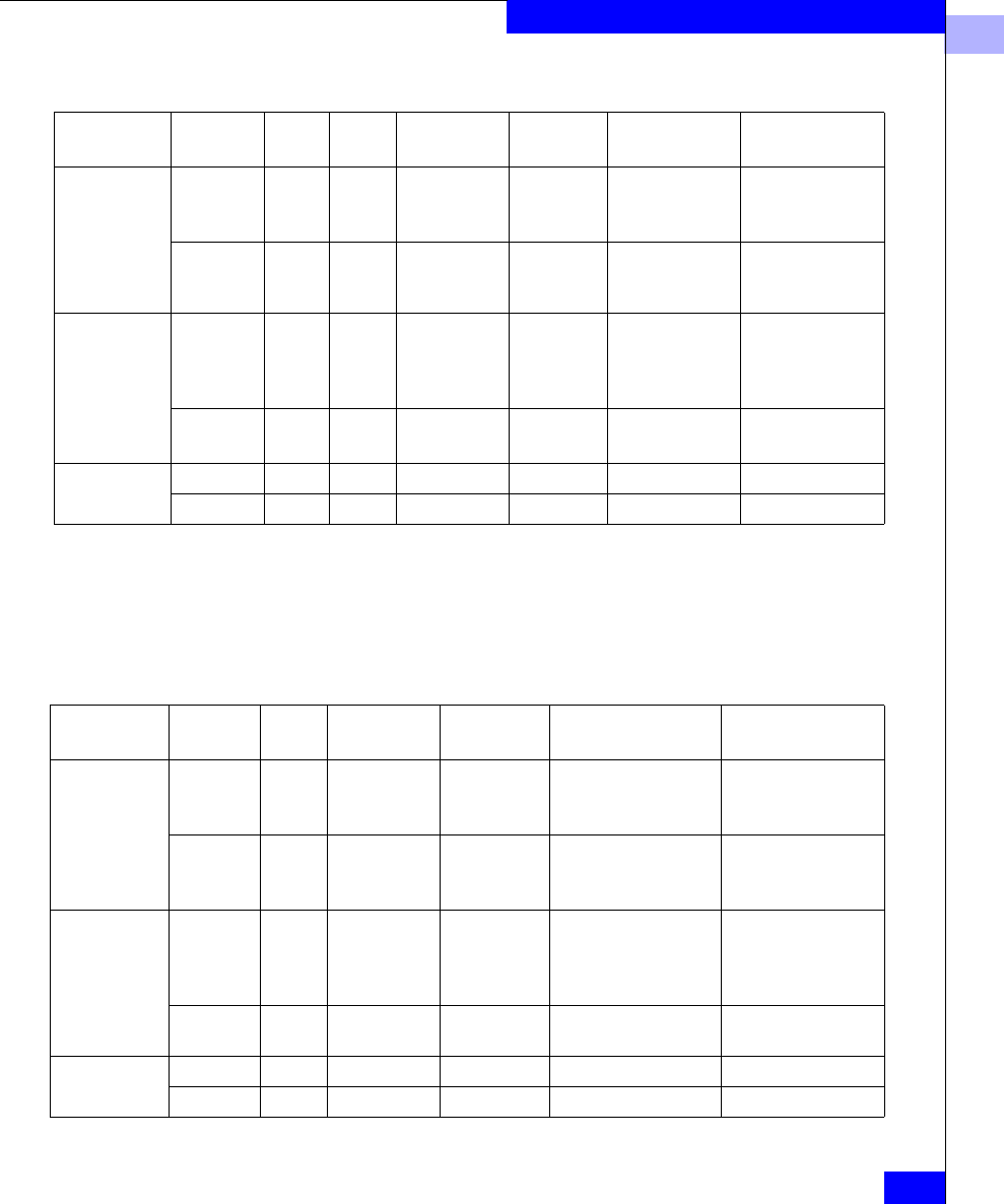
Table 5-1 High-Availability Options, Deskside Unshared Storage
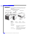
For rackmount systems, the standby power supply or supplies (SPS
or BBU) must be placed in a tray directly beneath the storage system.
Typically, any hubs in the cabinet mount at the top or bottom of the
cabinet. Rackmount options are as follows.
Table 5-2 High-Availability Options, Rackmount Unshared Storage
Deskside
System Type HA Level PDUs SPs LCCs
Power
Supplies Disks SPS Units
DPE Minimum 1 1 1 DPE
1 DAE
1 DPE
1 DAE
5 (without write
cache)
0 (without write
cache)
1 (write cache)
Maximum 2 2 4 (2 DPE
2 DAE)
4
(2 DPE
2 DAE)
10 (write cache
or RAID 3)
2
iDAE Minimum 1 1 n/a (10-slot)
2 (30-slot)
1 3 (without write
cache)
5 (write cache
or RAID 3)
0 (without write
cache)
1 (write cache
Maximum 2 2 n/a (10-slot)
4 (30-slot)
2 (10-slot)
6 (30-slot)
5 (write cache
or RAID 3)
2
DAE only Minimum 1 n/a 1 1 No minimum n/a
Maximum 2 n/a 2 2 No minimum n/a
Rackmount
System Type HA Level SPs LCCs
Power
Supplies Disks SPS Units
DPE Minimum 1 1 1 5 (without write
cache)
0 (without write
cache)
1 (write cache)
Maximum 2 2 (DPE)
18 (with 9
DAEs)
2 (DPE)
11 (with 9
DAEs)
10 (write cache or
RAID 3)
2
iDAE Minimum 1 n/a (10-slot)
4 (with two
DAEs)
1 3 (without write
cache)
5 (write cache or
RAID 3)
0 (without write
cache)
1 (write cache
Maximum 2 n/a 2 5 (write cache or
RAID 3)
2
DAE only Minimum n/a 1 1 No minimum n/a
Maximum n/a 2 2 No minimum n/a


