


Design Guide & Applications Manual
For VI-200 and VI-J00 Family DC-DC Converters and Configurable Power Supplies
vicorpower.com 800-735-6200 Applications Engineering 1-800-927-9474 Rev. 2.1
Page 20 of 88
9. EMC Considerations
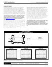
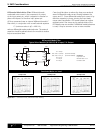
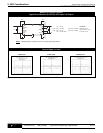
L1
C4
C1 = 100 μF
C2
a
–
C2
b
= 4,700 pF (Vicor Part # 01000)
C3
a
– C3
b
= 0.01 μF (Vicor Part # 04872)
C4 = 2.2 μF
L1 = 3,000 μH (Vicor Part # 31742)
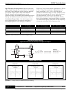
Conditions
Light Load = 3 A
Nominal Load = 15 A
Full Load = 30 A
+IN
GATE
IN
GATE
OUT
–IN
+OUT
+S
TRIM
–S
–OUT
C2
a
C1
C2
b
C3
b
C3
a
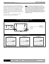
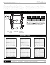
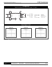
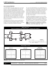
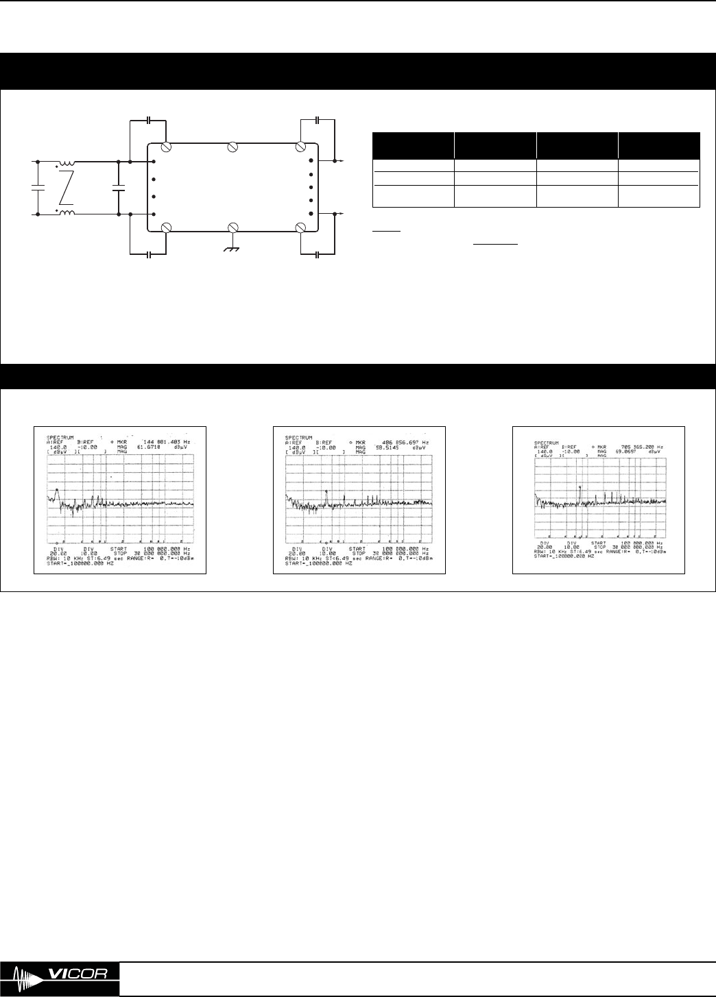
3 Amp Load 15 Amp Load 30 Amp Load
Conducted Noise vs. Load
Figure 9–3 — Conducted input noise, with common-mode choke
Typical Vicor Module (VI-230-CV)
48 V Input, 5 V Output
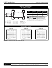
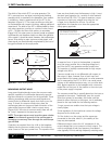
Three common-mode chokes are offered as standard accessories.
NOTE
: Common-mode filters may be common to one or
more modules, but only one
should be used with modules
interconnected via GATE IN’s or, GATE OUT to GATE IN. As
an example, Driver / Booster arrays or Drivers with GATE IN’s
tied together to provide a common disable function.
Part Inductance Maximum Resistance
Number Each Winding DC Current Each Winding
31743 1,000 µH 12 Amperes 6.5 mΩ
31742 3,000 µH 7 Amperes 18 mΩ
31943 2,163 µH 1 Ampere 42 mΩ