Installation Drawings
43
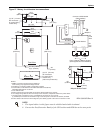
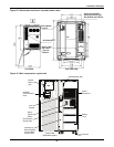
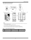
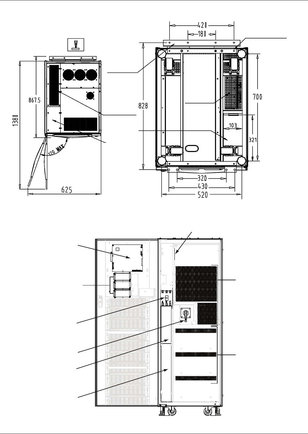
Figure 29 Dimensions continued—top and bottom views
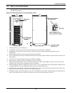
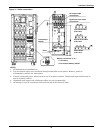
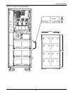
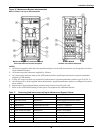
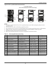
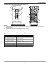
Figure 30 Main components—typical unit
Rear stabiliz-
ing foot
Air Exhaust
Power Cable
Entry Area
Top and
Bottom
Air
10mm dia. threaded
mounting holes 4 (typ).
See Notes 8 and 9 above.
TOP VIEW BOTTOM VIEW
Monitor
Board
(U2)
IntelliSlot
Communication
Ports
Input
Breaker
Input Breaker
A
ccess Plate
Internal and
External Battery
Terminal Block
Access Plate
Battery
Trays
Power
Electronics
Parallel Board (M3)
Front View
(with door open)
DPN U3812048
Rev. 1
Rotary
System
Switch


