381333–319 A
50 Hanover Road, Florham Park, New Jersey 07932–1591 USA
For sales or service call 1 800 800–2726 (ASCO) www.ascopower.com
ASCO POWER TECHNOLOGIES CANADA PO Box 1238, 17 Airport Road, Brantford, Ontario, Canada N3T 5T3
telephone 519 758–8450, fax 519 758–0876, for service call 1 888 234–2726 (ASCO) www.asco.ca
Operator’s
Manual
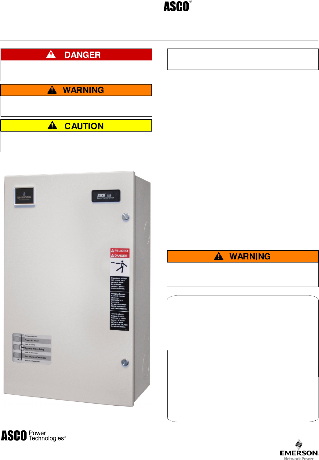
Seri es 185
Automatic Transfer Switches
100 t hrou gh 400 am pe re size s
DANGER is u sed in this m anual to warn of high
voltages capable of causing shock, burns, or death .
WARNINGisusedinthismanualtowarn
of possible personal injury.
CAUTIONisusedinthismanualtowarn
of possible equipment damage.
An ex p erienced l icen sed e lectric ian mu st in stall t he ATS .
100–230 am pere sizes
Refer to the outline and wiring drawings provided with
your ASCO Series 185 ATS for all installation details.
A SCO Series 185 A utomatic Transfer S w itches ( ATSs) are
Listed under Underwriter’s Laboratories St andard for
Tr ansfer Switch Equipment, U L–1008. They are i ntended
for use only in optional standby system s in accor dance with
the National Electrical C ode, NEC/NFPA 70, Article 702.
This AT S is for use with 2–wir e automatic start gene r ator s
only.
Refer to A ppl ication I nformaton 381339–292 t o confirm
that you hav e selec ted tha appropriate produc t for the
intend ed instal l atio n .
This automatic transfer sw itch is i n tende d for standby
pow e r applicaton s in re s ide n tial / lig ht com m e rcial use onl y.
This product is not intended for emergency
or life–support systems.
If you have mor e strin g e nt applic ation requirement s co ntact
A SCO Pow er Techno l og ies for other products suitabl e for
cr itic al appl ication s .
Rating Label
Eac h autom atic transfer switc h contains a rating lab el to
define the loads and fault circuit withstand / cl osing ratings.
Refer t o the lab el on the transfer switch for specific valu es.
Do not exceed the values on the rating label.
Exceeding the rating can cause personal
injury or serious equipment damage.
TABLE OF CONTENTS
page
INSTALLATION 1..........................
CONTROLLER 2–5........................
FUNCTIONAL TEST 6......................
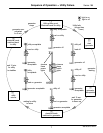
SEQUENCE OF OPERATION 7.............
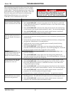
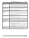
TROUBLESHOOTING 8–9..................
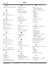
INDEX 10.................................


