


Chapter 4 Operator Control And Display Panel 27
HIPULSE U UPS Single Module And “1+N” (Expandable) 160/200/300/400kVA User Manual
Chapter 4 Operator Control And Display Panel
This chapter expounds the functions and use of the components on the operator control and display panel of the
HIPULSE U UPS, and provides LCD display information, including the LCD screen types, detailed menu messages,
prompt windows and UPS alarm message list
4.1 Introduction
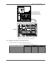
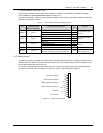
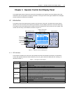
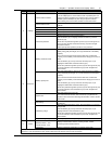
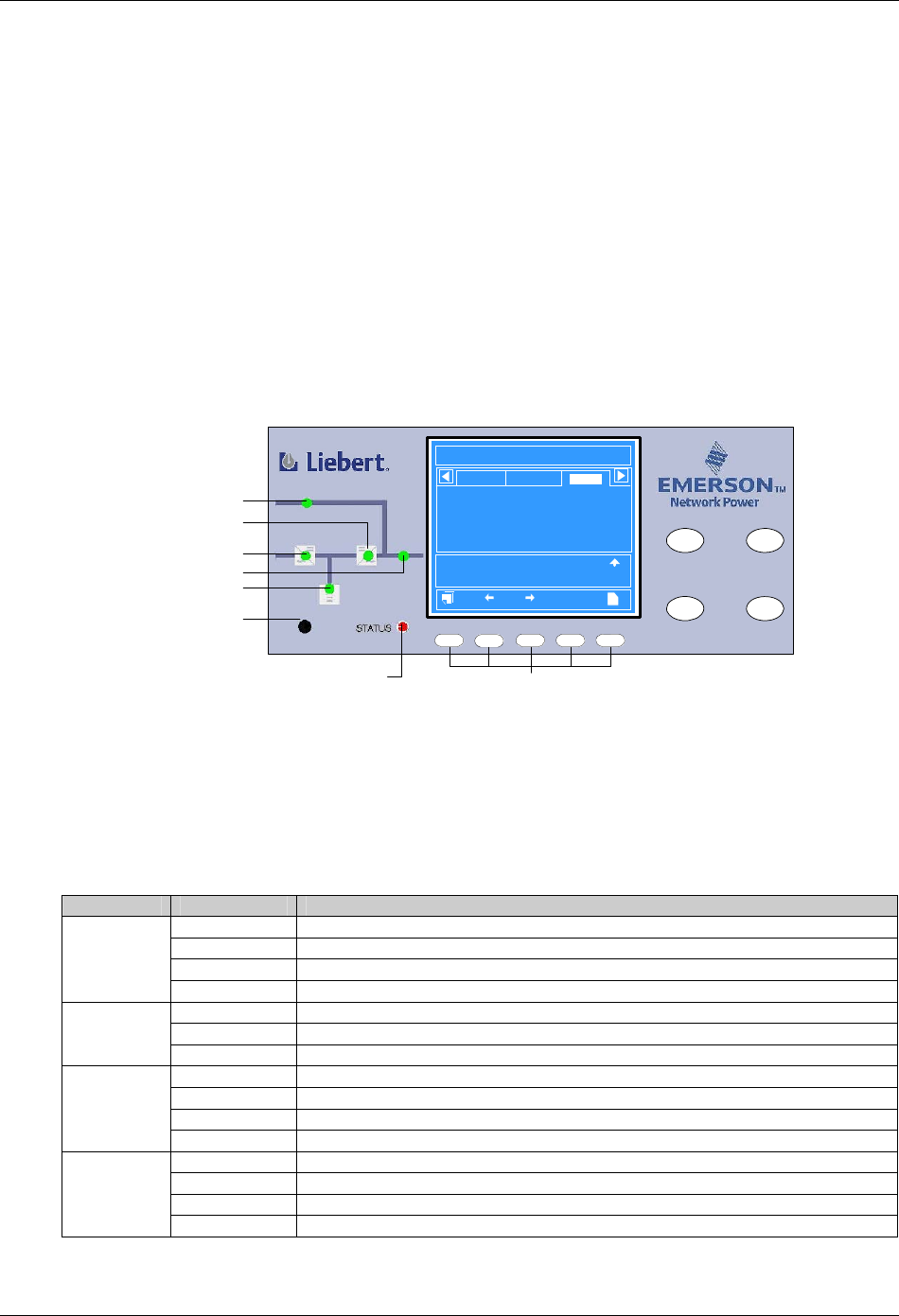
The operator control and display panel is located on the front door of the UPS. The panel is the access point for
operator control and monitoring of all measured parameters, UPS and battery status and of event and alarm logs.
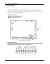
The operator control and display panel is divided into three functional areas: mimic power flow chart, graphic LCD
monitor with menu keys, control buttons, as shown in Figure 4-1.
INVERTER
ON
FAULT
CLEAR
F2
F4
HELPF1 F3
INVERTER
OFF
SILENCE
ON/OFF
12:30:36
Unit #1 Normal
?
Bypass
Main
Vphase V
Iphase A
Freq. Hz
Vline V
P.F.
A(AB)
220
20.5
50.1
380
0.99
B(BC)
220
20.5
50.1
380
0.99
C(CA)
220
20.5
50.1
380
0.99
Output
Input Breaker Closed 10-12 12:28:16
Manual Turn On 10-12 12:30:06
UPS in Normal Mode 10-22 12:30:16
200kVA-3X3
HIPULSE U
2006-01-01
Mimic power flow chart Control buttons
Battery LED
Buzzer
Graphic LCD monitor
with menu keys
Rectifier LED
Bypass LED
Inverter LED
Load LED
Alarm LED
LCD menu keys
Figure 4-1 Operator control and display panel
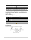
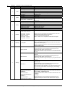
4.1.1 LED Indicators
The six LEDs mounted on the mimic flow chart represent the various power paths of the UPS, and indicate the
current UPS operational status and alarm status by color (red, green, yellow) and state (ON, OFF, flashing), as
described in Table 4-1.
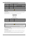
Table 4-1 Description of LED indicators
LED State Description
Steady green Rectifier in normal operation
Flashing green Input AC normal, but rectifier not operating
Steady red Rectifier f failed
Rectifier LED
OFF Rectifier not operating, input ac not available or out of normal range
Steady green Load on bypass power
Steady red Bypass not available, out of normal range or static bypass switch fault
Bypass LED
OFF Bypass normal, load not on bypass power
Steady green Battery normal, but discharging and powering the load
Flashing green Battery end-of-discharge pre-warning
Steady red Battery abnormal (failed, absent or polarity reversed) or battery circuit breaker abnormal
Battery LED
OFF Battery and battery circuit breaker normal, battery charging
Steady green Inverter normal and powering the load
Flashing green Inverter ON, starting up, synchronizing, or standing by (ECO mode)
Steady red Inverter failed
Inverter LED
OFF Inverter not operating