Installation and Configuration
17 Liebert
®
GXT3
™
5.3.1 Distribution Box Electrical Connections
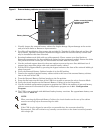
Electrical connections are made through a removable power distribution box that attaches to the rear
of the UPS.
• PD2-CE6HDWRMBS fits the 5000 and 6000VA models of the Liebert GXT3
• PD2-CE10HDWRMBS fits the 10,000VA model of the Liebert GXT3
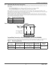
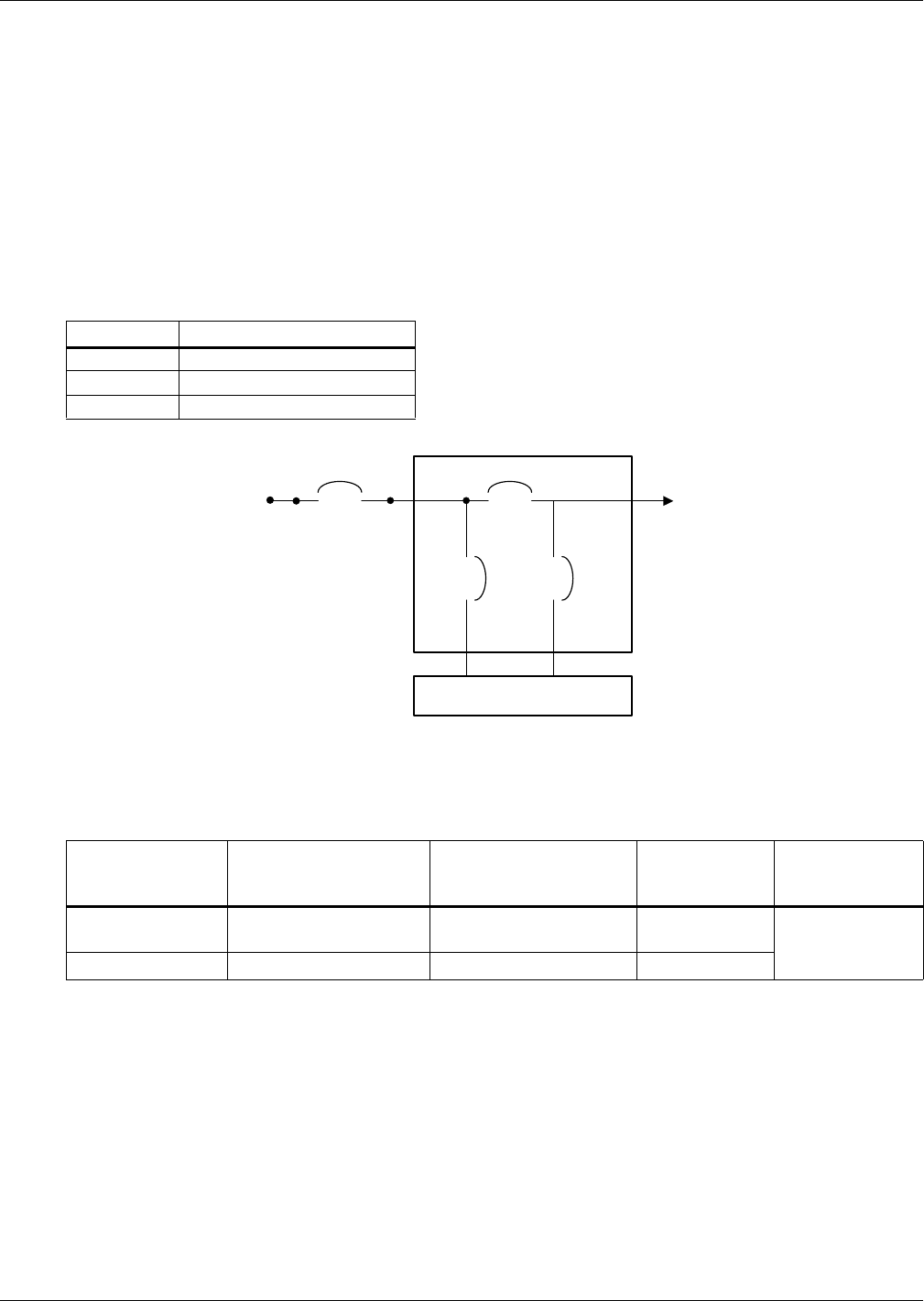
The installer must provide an upstream branch circuit breaker. The input circuit breaker on the
distribution box and the output circuit breaker on the rear of the power distribution box disconnect all
power between the main cabinet and the distribution box.
Models equipped with a manual bypass breaker pass bypass power directly to the bypass breaker
from the input terminal block. The input circuit breaker on the distribution box does not disconnect
power from the manual bypass breaker.
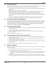
Figure 11 Distribution box electrical connections diagram
Terminal Block Connections—PD2-CE6HDWRMBS and PD2-CE10HDWRMBS
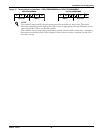
Conduit entry holes are provided on the rear and side of the box. Input and output wiring should not
share the same conduit. Emerson® recommends using strain relief when installing the wire.
Table 1 Branch circuit breaker ratings
Unit Rating Maximum Breaker Rating
5000VA D Type 32A
6000VA D Type 32A
10,000VA D Type 63A
Table 2 Electrical specifications
UPS Model
Recommended
(Maximum) External
Overcurrent Protection
Recommended Wire
(Including ground wire)
(75°C copper wire)
Maximum Wire
Accepted by
Terminal Block
Terminal
Tightening
Torque
GXT3-5000RT230
GXT3-6000RT230
32A 4mm
2
(10AWG) 6mm
2
(8AWG)
2.26 Nm (20 in-lb)
GXT3-10000RT230 63A 10mm
2
(6AWG) 16mm
2
(4AWG)
Mains Input
Input
CB
Output
CB
External
Branch CB
Output
MB CB
PD2-CE6HDWRMBS
and
PD2-CE10HDWRMBS
UPS-PFC, Battery Inverter


