


Ins
t
al
la
tion,
Opera
tion and
M
ai
nt
en
an
c
e
M
an
u
al
6
IO
-
70103
Re
v 0, 1/2013
Su
r
ge Pr
otectiv
e D
e
vi
ces
I
NS
T
ALL
ATI
ON
I
NST
RUCTI
ONS
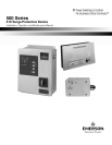
The Emerson Network Power
510 Serie
s Su
r
ge Pr
otec
ti
v
e
De
vi
ce
s (
S
PDs) are h
i
gh q
u
ali
ty
, h
i
gh
ener
gy su
r
ge
curren
t
di
ver
sion
s
ys
te
ms d
esi
gned
t
o pr
otec
t
se
nsiti
v
e equipm
en
t
from
dam
aging transi
en
t
v
ol
t
age su
rge
s. Prop
e
r ins
t
al
la
tion
is required
f
or
m
axi
mu
m
s
ys
te
m p
erform
an
ce.
The ins
t
all
e
r should p
erfor
m the
f
oll
o
wing s
tep
s
t
o
as
sure a
qu
ali
t
y ins
t
al
la
tion. The
en
tire ins
t
al
la
tion
m
an
u
al should be
re
ad b
ef
ore s
tar
ting ins
t
al
la
tion. Th
es
e inst
ruc
tions do n
o
t
replac
e
na
tio
n
al or local
e
le
ctr
ical
c
od
e
s.
C
hec
k applicable
e
le
ctr
ical
c
od
es to e
nsure
c
ompl
i
an
ce.
Ins
t
al
la
tion
of
the
S
PD
s
ys
tem
should
only
be
perfor
med
by qu
alified p
ers
onn
e
l.
1.
Insure t
ha
t all p
ow
e
r is r
em
ov
ed b
ef
ore beginning
ins
t
al
la
tion.
A qu
alified li
cens
ed
e
le
ctrici
an
sh
all
ins
t
all
all
e
le
ctr
ical
c
onne
c
tions.
2.
The
standard
S
PD
is
pr
ovi
ded
in
a
NEMA
1 (indoor),
NEMA12 (indoor)
or NEMA 4X
(outdoor)
rated
enclo
sur
es
sui
t
able
f
or
us
e in indoor or ou
t
door ins
t
al
la
tions.
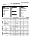
Verify
the SPD enclosure rating by referencing
position 11 in
the
Model Number Configuration tool on page 3.
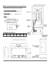
3.
Deter
mine wh
e
re the
S
PD is
t
o be mou
nted
, all
o
wing
f
or mini
m
um l
e
ngth
o
f wire b
etwee
n it
se
lf and the input
p
ow
e
r
ter
mi
n
als
o
f the
ser
vi
c
e
p
an
e
l. Pun
c
h or
c
ut the
prop
e
r hole s
iz
e
in the
si
de
o
f the
S
PD
clo
se
st
t
o the
knoc
k
out
t
o
be util
iz
ed in the
ser
vi
c
e
p
an
e
l.
(NEMA 4X
plastic enclosure units include a flexible conduit/nipple
accessory
no punching/drilling required in SPD)
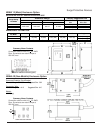
Dr
ill
mou
n
ting hol
e
s in
w
all
a
t loc
a
tion
p
ic
k
ed
f
or
S
PD n
ex
t
t
o
ser
vi
c
e
p
an
e
l
us
ing mou
n
ting dim
e
nsions
sh
o
wn
in
the
t
able
below.
Mou
nt
su
r
ge
suppr
ess
or
t
o
w
all
u
sing
appropriate size & type
mou
n
ting
hardw
ar
e.
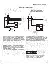
4.
C
onne
c
t b
l
ack wir
e
s (line or p
ha
s
e)
mark
ed L1/
A
, L2/B or
L3/C, the whi
t
e wire (n
e
utral)
mark
ed N, and the gre
e
n wire
(grou
nd)
mark
ed
G
,
o
f the
S
PD
u
sing the wire range lis
t
ed
below
.
T
o yi
e
ld the b
e
st p
erform
an
c
e
o
f the
S
PD within the
e
le
ctr
ical dist
r
ibution
s
ys
te
m,
kee
p all
c
ondu
ctor
s
a
s sho
r
t
a
s p
os
sible and
av
oi
d s
har
p b
e
nds.
5.
C
onne
c
tion
to the unit s summar
y a
lar
m
contac
ts s
h
all be
with
#18
22
AWG.
The
ra
tin
gs of
the
Form C
contac
ts
are
5 am
p
s
a
t 250
VA
C
m
axi
m
um with a p
ow
e
r
fact
or
o
f
1.0.
F
or additio
n
al i
nfor
ma
tion,
see Monitor
in
g sec
tion.
6.
A
pply p
ow
er
. The su
r
ge pr
otect
or is fully op
era
tio
n
al
wh
e
n the
GR
EEN
LED s
on
the
modul
es
(when applicable),
and
the
fro
nt of
the
enclo
sure are illumi
na
ted
. If the
G
REEN
LED s are ex
tinguished or a RED LED
is
illumi
na
ted, c
heck
to e
nsure
t
ha
t p
ow
er
is
applied
t
o the
SPD.
If
an
abno
rm
al
indic
a
tion
is
pr
es
en
t,
rem
ov
e power t
o the
S
PD and
contac
t
Em
ers
on N
etwor
k
P
ow
e
r Su
r
ge Pr
otec
tion
a
t
1-
800
-
288
-
6169 or 1
-
607
-
721
-
8840
.
7.
Per
iodically moni
t
or the s
tatu
s
of the LED s. R
edu
c
ed
pr
otec
tion
e
xists
i
f the
GREEN LED s are ex
tinguished or
the RED LED is illumi
na
ted
. Pl
eas
e
contac
t Em
ers
on
Networ
k
P
ow
e
r
Su
r
ge
Pr
otec
tion
a
t
1-
800
-
288
-
6169
or
1-
607
-
721
-
8840.
8.
The pr
otec
tion modul
e
s in th
es
e
SPD s
ma
y be
replace
abl
e
,
contac
t Em
ers
on N
etwor
k
P
ow
e
r Su
r
ge
Pr
otec
tion
f
or r
eplacemen
t.
If
the SPD
model
is
a Wye c
onfi
gured
unit
(4W+G),
and a
Ne
ut
r
al
c
on
nec
tion is n
o
t
av
ailabl
e
, pl
e
ase
c
on
tac
t
factory.