Wiring Considerations
24
7.2 Control Wiring
Control wiring must be flexible stranded, tinned copper and run in individual separate steel conduits.
Control wiring must be separated from power wiring. In addition, each control wiring cable group
should be run in a separate conduit to minimize control signal interference.
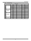
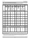
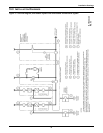
Refer to the Control Connection Locations and Control Wire Lists, Figures 27 through 42. Notice
that there are nine cable groups in a typical system:
• Cable group 1 carries signals for the Module Battery Disconnect.
• Cable group 2 is for the remote communications options: modem, remote terminal and remote
CRT.
• Cable group 3 carries signals for the Remote Emergency Module Off and Remote Emergency
Power Off.
• Cable group 4 carries signals for the optional Remote Monitor Panel.
• Cable group 5 is for the optional SiteScan system.
• Cable group 6 carries signals for the reduced battery charge limit and the reduced input current
limit.
• Cable group 7 carries signals to and from the maintenance bypass switchgear.
• Cable groups 20 and 21 carry signals for general housekeeping, modules to SCC.
Other cable groups will be required for other optional equipment. If your system has any installed
options, special wire lists will be included in your Submittal Drawing Package. Contact your Liebert
Sales Representative for assistance if the submittal drawings have been lost or misplaced.
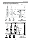
Figures 27 and 28 show the typical location of control connections inside the UPS and SCC. The
position of a particular control connection may be different for your system, depending on the model
and the installed options.
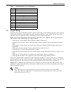
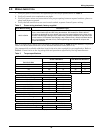
Table 1 Abbreviations for circuit breakers
BFB Bypass Feeder Breaker
BIB Bypass Input Breaker
CB1 Module Input Breaker
CB2 Module Output Breaker
MBB Maintenance Bypass Breaker
MBD Module Battery Disconnect
MBFB Maintenance Bypass Feeder Breaker
MIB Maintenance Isolation Breaker
RIB Rectifier Input Breaker
SBB System Bypass Breaker
SSB Static Bypass Switch
UOB UPS Output Breaker
NOTE
The UPS control and communication wiring are considered Class 2 circuits by NEC
standards. However, NEC Class 1 wiring methods are required for these circuits to ensure
proper operation of the UPS.


