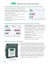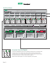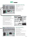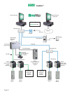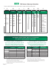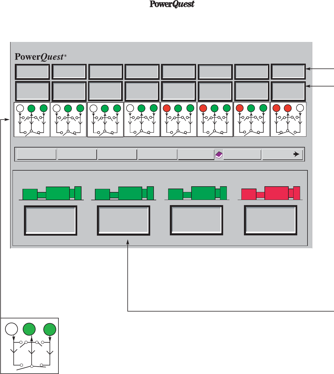
Summary Screen
Convenient One-Line Diagram
• Colored icons highlighted to show source availability and which source is connected to load.
• Contacts move on icon to indicate main contact position of transfer and bypass switch.
(Automatic transfer and automatic transfer and bypass isolation switches must be provided
with optional accessory 14 auxiliary contacts shown on page 14.)
• Bypass switch contacts appear on icon when configured by user input data.
1901 lavg
548 KW
1901 lavg
548 KW
1901 lavg
548 KW
1901 lavg
548 KW
1901 lavg
548 KW
1901 lavg
548 KW
1901 lavg
548 KW
472 lavg
136 KW
208 NVca
0 EVca
OTTS
OTTS
OTTS
OTTS
OTTS OTTS
OTTS
OTTS
E
L
N
E
N
E
L
N
E
N
Engine 1 Stopped
Engine 2 Stopped
Engine 3 Stopped Engine 4 Running
0 KW Total
0.00 Frequency
0.00 Power Factor
0 Vavg.
0 lavg.
0 KW Total
0.00 Frequency
0.00 Power Factor
0 Vavg.
0 lavg.
0 KW Total
0.00 Frequency
0.00 Power Factor
0 Vavg.
0 lavg.
136 KW Total
60.01 Frequency
0.82 Power Factor
208 Vavg.
472 lavg.
E
L
N
E
N
E
L
N
E
N
E
L
N
E
N
E
L
N
E
N
E
L
N
E
N
E
L
N
E
N
ATS 1
208 NVca
0 EVca
ATS 2
208 NVca
0 EVca
ATS 3
208 NVca
0 EVca
ATS 4
208 NVca
208 EVca
ATS 5
208 NVca
208 EVca
ATS 6
208 NVca
208 EVca
ATS 7
0 NVca
208 EVca
ATS 8
TD Bypass
Re-TransferTransferPrevious
?
ATS 9-16
Re-Scan
ATS 1 - 8 Summary Screen
ATS 1 - 8 Summary Screen
ASCO
ᓼ
ASCO
ᓼ
E
E
L
N
N
Page 18
®
ASCO


