INSTALLATION (continued)
1 --- 3
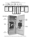
Functional Test
The Functional Test consists of three checks:
❐ 1 — Manual OperationTest, pages1–3 through1–6
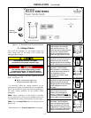
❐ 2—VoltageChecks,page1–7
❐ 3 — Electrical Operation, page 1–8
Do these checks in the order presented
to avoid damaging the ATS.
Read all instructions on the Wiring Diagram and labels
affixed to t he ATS. Note the control features that are
provided and review their operation before proceeding.
Continue to 1–ManualOperationTest starting below.
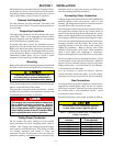
1 – Manual Operation Test
A detachable operator handle is provided on the transfer
switch fo r mai nten an c e purpo s es on ly.Manualoperation
of the transfer switch must be checked before it is
operated electrically.
Do not manually operate the transfer switch
until both power sources are disconnected:
open both circuit breakers.
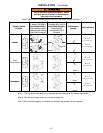
1. Select the appropriate swi tch design / amp. size and
follow directions for installing and using the handle:
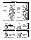
150–1200 amp J, H–designs Fig. 1-3, -4, -6 thru -11.
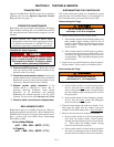
Attach the manual handle onto the shaft hub, left
side of the operator.
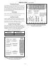
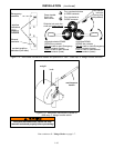
1600 – 3000 amp. G–design See Figures 1-5, 1 -12.
Installthehub (withpin
) ontothe shaft andinsert the
manualfirmlyintothesideholeinthehub. Pushin
or pull out hub to engage opposite source contacts.
4000 amp. F–design SeeFigure1-13.
Insert the manual handle into the hole in the weight.
2. Move t he handle as shown to manually operate the
Transfer Swit ch. The switch should operate smooth-
ly without binding. If it does not, check for shipping
damage or construction debris. Repeat the manual
operation check on the other Transfer Switch.
3. Retur n th e tran sfer s w itc h to th e N (closed on normal)
position. If removable, remove the maintenance
handle and store it on the transfer switch in the place
provided.
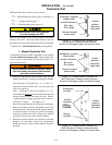
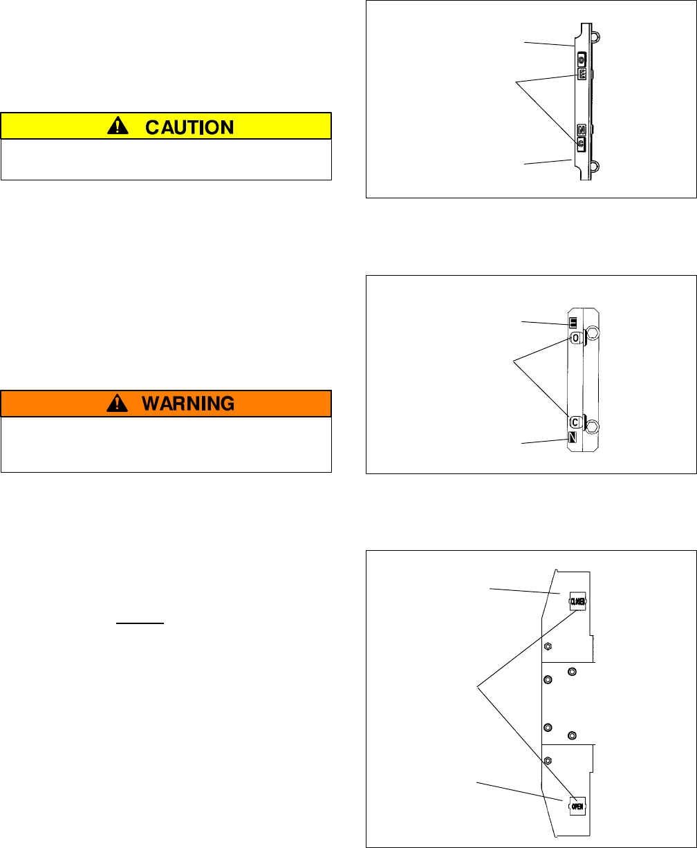
window indicators
O is open
C is closed
Emergency contacts
(upper shaft)
Normal contacts
(lower shaft)
contact
position
indicators
(right side)
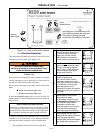
Figure 1-3. Contact position indicators on
150–600 amp. J–design transfer switches .
Shown with Emergency open and Normal closed.
window indicators
O is open
C is closed
Emergency contacts
(upper shaft)
Normal contacts
(lower shaft)
contact
position
indicators
(right side)
Figure 1-4. Contact position indicators on
800–1200 amp. H–design transfer switches .
Shown with Emergency open and Normal closed.
window
indicators
OPEN or
CLOSED
Emergency
contacts
Normal
contacts
contact
position
indicators
(left side)
Figure 1-5. Contact position indicators on
1600–3000 amp. G–design transfer switches .
Shown with Emergency closed and Normal open.


