


INSTALLATION (continued)
1 --- 3
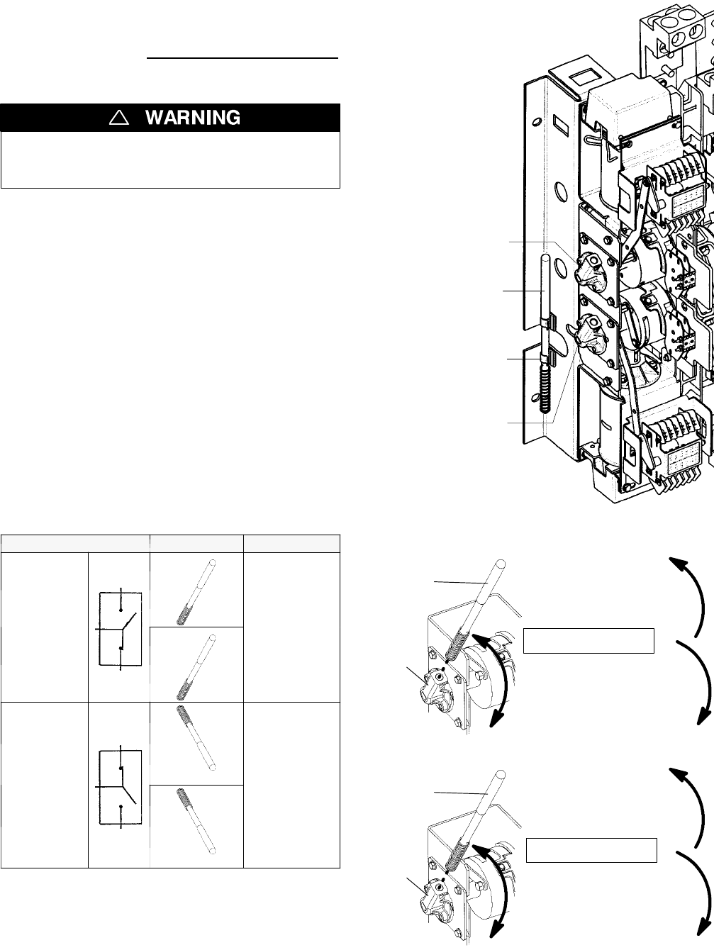
1 – Manual Operation Test
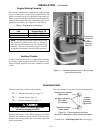
A d etachable m aintenance handle is provided on the frame
of the Transfer Switch for maintenance purposes only
.
Manual operation of the transfer switch should be
checked before it is energized (operated electrically).
Do not manually operate the transfer switch
until both power sources are disconnected:
open both circuit breakers.
!
1. After deenergizing both power sources, open the
enclosuredoor. Locate and removethemaintenance
handle from the clips on the left side of the tra nsfer
switch frame. Insert the handle into the hole in the
molded hub on the left side of the operator. See
Figures 1–3 through 1–5 and Table B.
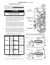
2. Move the maintenance handle up or down as shown
tomanually operatethe transferswitch. The transfer
switch should operate smoothly withoutbinding. Ifit
does not, check for shippi ng damage or construction
debris. Operate bothupper andlower contactshafts.
3. Retur n th e t ran sfer switc h t o t he No rm al position.
Observe that the window indicators (right side) show
the upper shaft O (Emergency open) and the lower
shaft C (N ormal c l osed). Remove the maintenance
handl e and store it on the frame in the clip s provided .
Table B . Maintenance handle positions.
A TS Position Handle Indicators
N
o
r
m
a
l
E
up
E=O
uppercontactsopen
N
orma
l
N
up
N=C
lowercontactsclosed
E
m
e
r
g
e
n
c
y
E
down
E=C
upper contactsclosed
E
mergency
N
down
N=O
lowercontactsopen
Note: If Normal and Emergency connections are
reversed this operation is also reversed.
Now continue to 2–VoltageChecks on the next page.
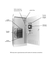
maintenance
handle
left side of
transfer switch
clip
Emergency source
contact shaft hub
Normal source
contact shaft hub
Figure 1-3. Maintenance handle storage location.
HubsshownwithNormalclosed&Emergencyopen.
handle
hub
UP opens the
Emergency source
contacts
DOWN closes the
Emergency source
contacts
frame
UPPER SHAFT
Figure 1-4. Emergency (upper shaft) operation.
handle
hub
UP closes the
Normal source
contacts
DOWN opens the
Normal source
contacts
frame
LOWER SHAFT
Figure 1-5. Normal (lower shaft) operation.