


INSTALLATION (continued)
1 --- 4
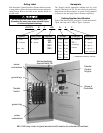
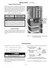
Transfer Switch
Connected
To
Normal
Transfer Switch
Connected
To
Emergency
Normal
Source
Accepted
Emergency
Source
Accepted
Transfer
Control
Retransfer
Delay
Bypass
Transfer
Test
HOLDFOR
15SECONDS
RED
RED
GREEN
GREEN
(
)
Automatic Closed Transition
Transfer Switch
observe
these lights
Extended
Parallel
Time
Failure
To
Synchronize
TS
Locked
Out
Alarm
Reset
Closed
Transition
Bypass
RED RED RED
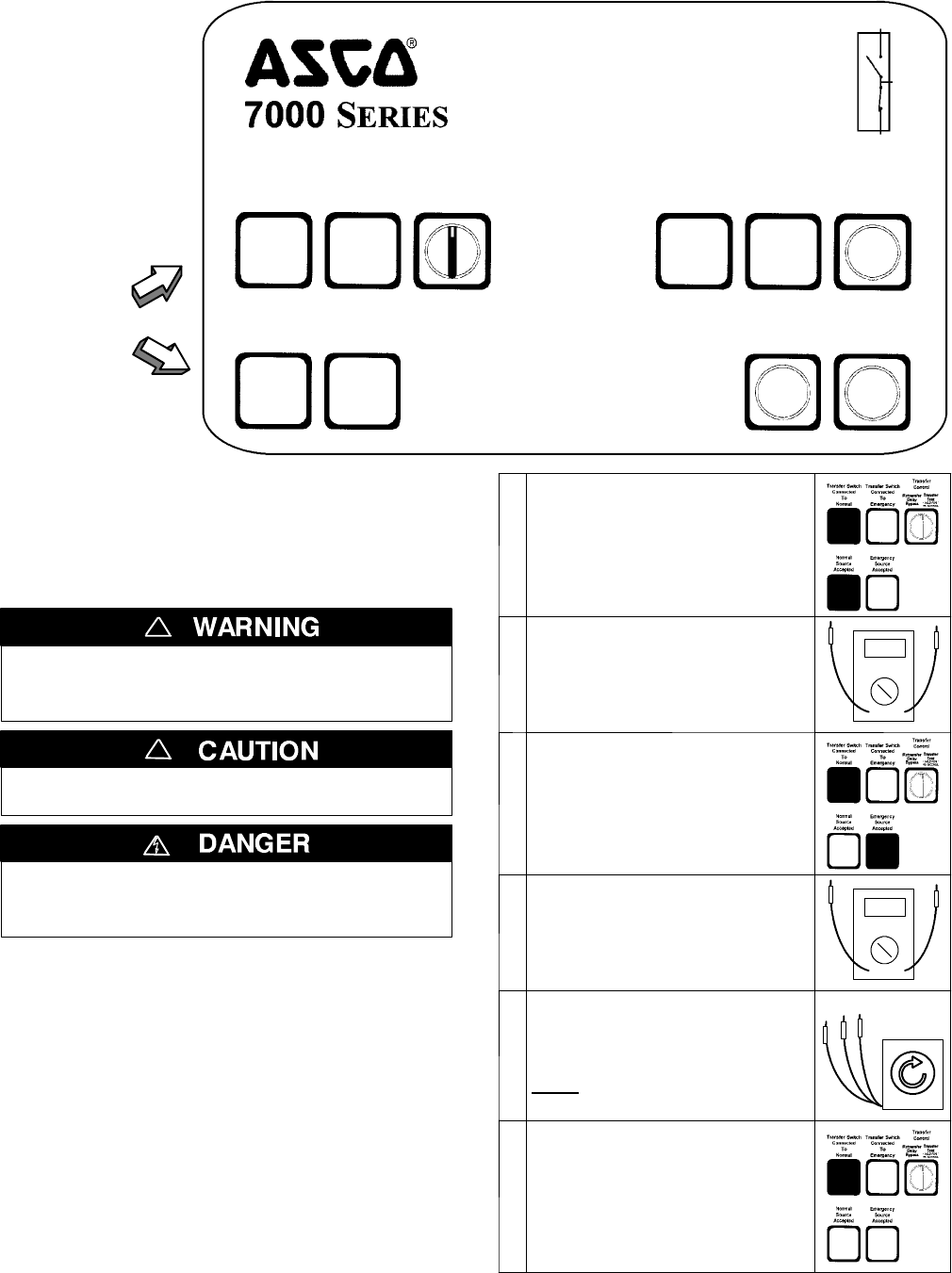
Figure 1-6. Standard controls and indicators.
2 --- V o l t a g e C h e c k s
First check nameplat e on transfer switch; rated voltage
mustbethesameasnormalandemergencylinevoltages.
Before energizing the switch check to be sure
that both normal and emergency contacts are
notleftintheclosedposition.
!
Verify that the feeders have been
connected to the proper lugs.
!
Useextremecautionwhenusingameterto
measure voltages. Do not touch power termi-
nals; shock, burns, or death could result !
Performsteps 1 through6 at the right. Observe the status
lights. See Figure 1---6.
■ Black square means light is on.
❐ White square means light is off.
* If necessary, adjust voltage regulator on the generator
according to the manufacturer’s recommendations. The
Automatic Transfer Switch will respond only to the rated
voltage specified on the Transfer Switch nameplate.
Note: Refer to Section 3 of Group 5 Controller U ser’s
Guide 381333–126 for how to display the Status of the
ATS and the Voltage and Frequency of each source.
Now continue to 3 --- Elect ri c al Operatio n on next page.
1
Close the normal source circuit
breaker. The Transfer Switch
Connected To Normal and the
Normal Source Accepted lights
should come on.
2
Use an accurate voltmeter t o
check phase to phase and
phase to neutral voltages pres -
entatthetransferswitchnormal
source terminals.
3
Close the emergency source
circuit breaker. (Start generator,
if necessary.) The Transfer
Switch Connected To Normal &
Emergency Source Accepted
lights should come on.
4
Use an accurate voltmeter t o
check phase to phase and
phase to neutral voltages pres -
ent a t t he transfer switch emer-
gency source terminals.*
5
Useaphaserotationmeterto
check phase rotation of emer-
gency source; it must be the
same
as the normal source.
A
B
C
6
Shut down the engine–genera-
tor, if applicable. The Emergen-
cy Source Accepted light should
go off. Then put the starting
control selector switch (on the
generator set) in the automatic
position. Close enclosure door.