


Figures ix
Figure Page
Figures
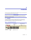
1-1 The 2H252-25R SmartSwitch 2200.................................................................................1-1
3-1 Tabletop or Shelf Installation...........................................................................................3-4
3-2 Attaching the Strain-Relief Bracket .................................................................................3-6
3-3 Attaching the Rackmount Brackets .................................................................................3-7
3-4 Installing the Device in a Rack ........................................................................................3-7
3-5 2H252-25R Rear View ....................................................................................................3-8
3-6 Connecting the Twisted Pair Segment ..........................................................................3-10
3-7 Schematic of Straight-Through and Crossover Cables .................................................3-11
4-1 LANVIEW LEDs ..............................................................................................................4-2
4-2 RESET Button .................................................................................................................4-9
B-1 Removing the Chassis Cover......................................................................................... B-4
B-2 Mode Switch Location .................................................................................................... B-5
B-3 SIMM Slot Locations ...................................................................................................... B-7
B-4 Installing the DRAM........................................................................................................ B-8
B-5 HSIM and VHSIM Connector Locations ......................................................................... B-9