


Completing the Installation
3-26 Installation
Completing the Installation
CompletingtheDFEmoduleinstallationdependsonifthemoduleisbeinginstalledin:
•anewDFEmodulesystem(referto“CompletingtheInstallation”onpage 3‐26),or
•anestablished,operatingDFEmodulesystem(referto“CompletingtheInstallationof
aDFE‐GoldModuleinanExistingSystem”onpage 3‐28).
Completing the Installation of a New System
InanewsystemofDFEmodules,oneoftheinstalledDFEmoduleswillbecomethe
managementmoduleonchassispowerup,andallDFEmoduleswillautomaticallybeset
tothefactorydefaultvalues.Acompletelistofthefactorydefaultvaluesareprovidedin
Chapter3oftheEnterasys
MatrixDFE‐GoldSeriesConfigurationGuide.
AfterinstallingallDFE‐Gold modulesintothehostchassisandmakingtheconnectionsto
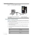
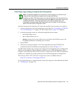
thenetwork,proceedto“First‐TimeLog‐InUsingaConsolePortConnection”on
page 3‐27toaccessthemodulemanagementstartupscreenfromyourPC, terminal,or
modemconnection.
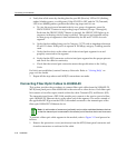
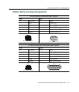
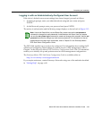
Modem Port Adapter Wiring and Signal Diagram
RJ45 DB25
Pin Conductor Pin Signal
1 Blue 2 Transmit (TX)
2 Orange 8 Data Carrier Detect (DCD)
4 Red 3 Receive
5 Green 7 Ground (GRD)
6 Yellow 20 Data Terminal Ready (DTR)
8 Gray 22 Ring Indicator
RJ45 Connector (Female)
Pins
81
DB25 Connector (Male)
Pins
14 25
113