


Memory Locations and Replacement Procedures
Matrix DFE-Gold Series Modules Hardware Installation Guide B-7
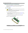
DIMM Replacement Procedure (4H4282-49 and 4H4283-49)
ToremoveandreplacetheDRAMSIMMonthe4H4282‐49or4H4283‐49,referto
Figure B‐8andFigure B‐9respectively,andproceedasfollows:
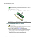
Removing the DRAM SIMM
1. IfthereisanoptionalNEMinstalledonthemainboardofthe4H4282‐49or
4H4283‐49,proceedtostep1a.Otherwiseproceedtostep2.
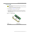
a. RemoveandsavethethreescrewsattachingtheNEMtothestandoffonthemain
boardandfrontpanel.
b. LifttheNEMstraightup
andoffthetwomoduleconnectorsonthemainPC
board.
Caution: Observe all Electrostatic Discharge (ESD) precautions when handling sensitive
electronic equipment.
Precaución: Al trabajar con equipos electrónicos sensibles, tome todas las precauciones
de seguridad para evitar descargas de electricidad estática.
Note: Prior to removing the DRAM SIMM in a 4H4282-49 or 4H4283-49, you must remove
the Network Expansion Module to gain access to the DRAM SIMM memory and
connector.
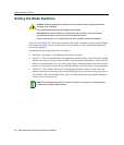
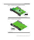
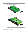
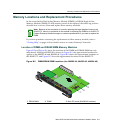
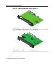
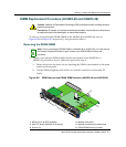
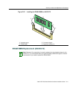
Figure B-8 NEM Removal and DRAM SIMM Location (4H4282-49 and 4H4283-49)
1 NEM (not on all DFE modules) 4 Module front panel
2 Main PC board (4H4282-49 is shown) 5 Module connectors on main board
3 Screws (3) 6 DRAM SIMM memory module
4H4282-49
F
AST ENET
DFE
1
2
3
4
5
6
➃
➀
➁
➂
➄
➅