


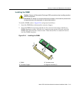

Memory Locations and Replacement Procedures
B-12 Mode Switch Bank Settings and Optional Installations
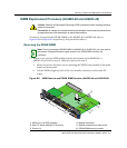
DIMM Replacement Procedure (All DFE Modules)
IntheeventthattheDIMMneedstobereplaced,thefollowingsectionsexplainhowto
removeandinstalltheDIMM.Ifyouhavequestionsconcerningthereplacementofthe
DIMM,referto“GettingHelp”onpage xviiifordetailsonhowtocontact
Enterasys Networks.
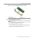
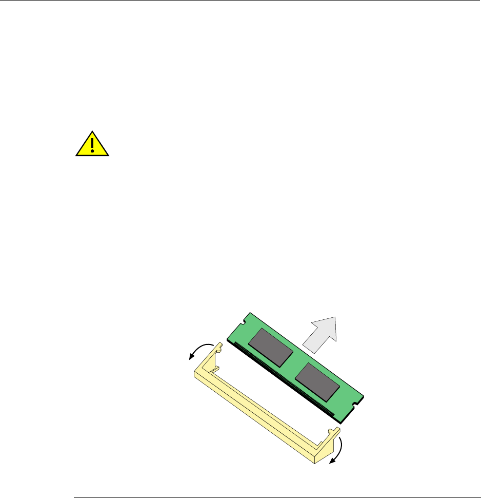
Removing the DIMM
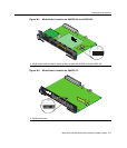
ToremovetheexistingDIMM,proceedasfollows:
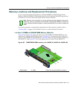
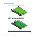
1. LocatetheDIMMconnectoronthemainPCboard.ReferbacktoFigure B‐5forthe
DIMMlocationoneitherthe4H4282‐49or4H4283‐49.ReferbacktoFigure B‐6forthe
locationonthe4H4203‐72.
2. Pushtheconnectorarmsawayfrom
theDIMM,asshowninFigure B‐13,and
simultaneouslylifttheDIMMenoughtoreleaseitfromtheconnectorfingers.
3. RotatetheDIMMupwards,thenremoveitfromtheconnectorfingers.
Caution: Observe all Electrostatic Discharge (ESD) precautions when handling sensitive
electronic equipment.
Precaución: Al trabajar con equipos electrónicos sensibles, tome todas las precauciones
de seguridad para evitar descargas de electricidad estática.
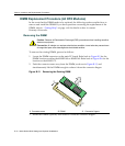
Figure B-13 Removing the Existing DIMM
1 Connector arms 2 DIMM 3 Connector fingers
À
À
Á
Â