


Connecting Switches to the RPS
2-5
2
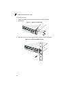
Desktop or Shelf Mounting
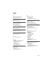
1. Attach the four adhesive feet to the bottom of the first RPS unit.
Figure 2-3. Attaching the Adhesive Feet
2. Set the device on a flat surface near an AC power source, making sure there
are at least two inches of space on all sides for proper air flow.
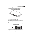
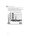
Connecting Switches to the RPS
Caution: DO NOT connect the RPS to an AC power source until DC power cords have
been connected to the supported switches.
To connect switches to the RPS, refer to Figure 2-4 and Figure 2-5 and proceed as
follows:
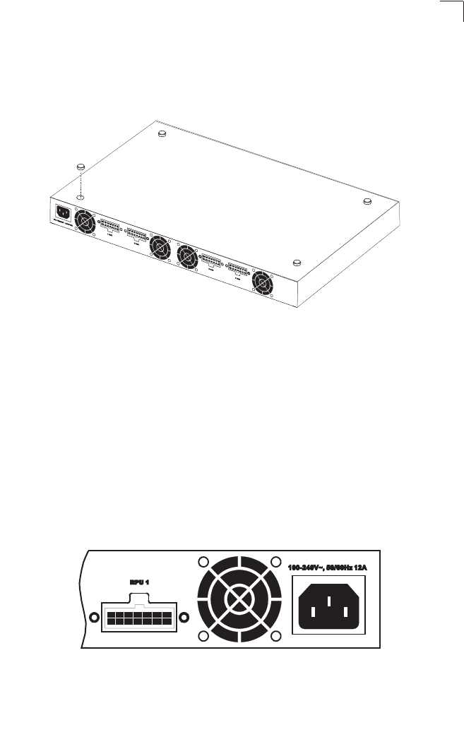
1. Power up the switch by connecting one end of the AC cord to the AC receptacle
on the supported switch, and the other end to a grounded power outlet.
Figure 2-4. Power Receptacle
2. Connect one end of a DC cord to the redundant power receptacle on the
supported switch and the other end to an available receptacle on the RPS.
3. Repeat steps 1 and 2 for connecting up to four supported switches to the RPS.
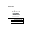
Rear
P
anel