


ETX-945 User Manual 1.00 www.diamondsystems.com Page 30
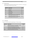
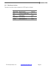
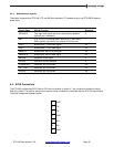
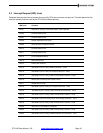
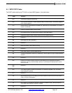
4.4.4 Miscellaneous signals
These pins implement the ETX-945’s I
2
C and SM Bus interfaces, PC-speaker output, and RTC/CMOS backup
power input.
Signal Name
Signal Function
Direction
SPEAKER
This logic-level signal can drive a piezoelectric speaker
(typically via a transistor)
O
BATT
2.4V to 3.3V DC backup power input for RTC and CMOS
RAM; typically connects to an external 3V lithium cell
I
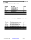
I2CLK
Bidirectional I
2
C Bus clock signal
I/O
I2DAT
Bidirectional I
2
C Bus data signal
I/O
SMBCLK
Bidirectional SM Bus clock signal
I/O
SMBDATA
Bidirectional SM Bus data signal
I/O
KBINH#
Keyboard inhibit signal
In
OVCR#
USB over-current detected
In
ROMKBCS#
Reserved; do not connect
n/a
EXT_PRG
Reserved; do not connect
n/a
GPCS#
Reserved; do not connect
n/a
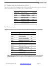
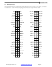
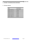
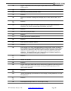
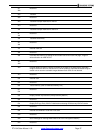
4.5 SATA Connectors
The ETX-945 provides two SATA (Serial ATA) drive interfaces on a pair of 7-pin connectors located on the top
side of the board. The position and pinout of each of these connectors is compliant with the ETX 3.0 Specification.
The signal assignment appears below.
1
GND
2
TX+
3
TX-
4
GND
5
RX+
6
RX-
7
GND