


RTC - 72421 / 72423
Page - 13 MQ - 162 - 03
4. CF register (control register F)
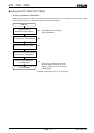
(1) RESET bit (D0)
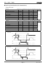
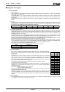
Writing 1 to the RESET bit clears the sub-second bits of the internal counter down to the 1/256-seconds counter. The reset
continues for as long as the RESET bit is 1. End the reset by writing 0 to the RESET bit. If the level of the CS
1
pin goes low,
the RESET bit is automatically cleared to 0.
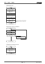
(2) STOP bit (D1)
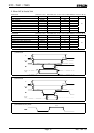
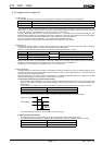
Writing 1 to the STOP bit stops the clock of the internal counter from the 1/8192 second bit onward. Writing 0 to the STOP bit
restarts the clock.
This function can be used to create a cumulative timer.
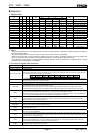
(3) 24/12 bit (D2)
Set the 24/12 bit to select either 12-hour clock or 24-hour clock as the timer mode. In 12-hour clock mode, the PM/AM bit is
used.
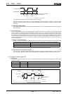
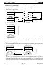
i. Switching between 12-hour clock and 24-hour clock
Writing 1 to the 24/12 bit selects 24-hour clock mode. In 24-hour clock mode, the PM/AM bit is inoperative and is always
0. Writing 0 to the 24/12 bit selects 12-hour clock mode. In 12-hour clock mode, the PM/AM bit becomes valid. It is 0 for
a.m. times and 1 for p.m. times.
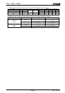
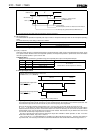
ii. Overwriting the 24/12 bit
Overwriting the contents of the 24/12 bit could destroy the contents of the registers from the H1 register upward (from the
1-hour digit upward). Therefore, before overwriting the 24/12 bit, it is necessary to save the contents of the hour (H1,
H10), day (D1, D10), month (MO1, MO10), year (Y1, Y10), and day-of-the-week (W) registers, then re-write the data back
into the registers to suit the new timer mode, after overwriting the 24/12 bit.
(4) TEST bit (D3)
The TEST bit is used by EPSON for test purposes. Operation cannot be guaranteed if 1 is written to this bit, so make sure
that it is set to 0 during power-on initialization.