


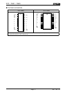
RTC - 72421 / 72423
Page - 10 MQ - 162 - 03
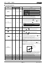
2. CD register (control register D)
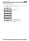
(1) HOLD bit (D0)
Use the HOLD bit when accessing the S1 and W registers. For details, see "Read/write of S1 to W registers".
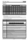
HOLD bit Function HOLD bit
0 The BUSY bit is always 1 (the BUSY status cannot be checked).
1 The BUSY status can be checked. When the HOLD bits is 1 and the BUSY bit is 0, read and write are enabled.
When the HOLD bit is 1, any incrementation in the count is held within the RTC. The held incrementation is automatically
compensated for when the HOLD bit becomes 0. (Second and subsequent incrementations are ignored.) Therefore, if the
HOLD bit is at 1 for two or more seconds in succession, the time will be slightly slow (delay). Make sure that any access to
the S1 to W registers is completed within one second, then clear the HOLD bit to 0.
The status of the BUSY bit remains as set while the HOLD bit is at 1. If the HOLD bit is not cleared temporarily to 0, the
BUSY bit will not indicate any change within the RTC of the BUSY status. Therefore, when checking the status of the BUSY
bit, write 0 to the HOLD bit each time the BUSY bit is read, to update the status of the BUSY bit.
If the CS1 pin goes low while the HOLD bit is 1, the HOLD bit is automatically cleared to 0.
There is no need to use the HOLD bit when accessing the control registers (C
D
, C
E
, and C
F
).
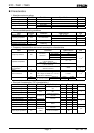
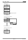
(2) BUSY bit (D1)
The BUSY bit indicates whether or not the digits from the seconds digit onward are being incremented, and is used when
accessing the S1 to W registers. For details, see "Read/write of S1 to W registers".
There is no need to check the BUSY bit when accessing the control registers (CD, CE, and CF).
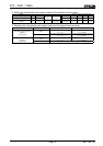
BUSY bit Significance of the BUSY bit Condition Remarks
0 Access enable The RTC is not counting
1 Access disabled
HOLD=1
The count has been incremented in the RTC (190
µ
s Max.)
1 BUSY is always 1 HOLD=0 The count cannot be checked
The status of the BUSY bit remains as set while the HOLD bit is at 1. If the HOLD bit is not cleared temporarily to 0, the
BUSY bit will not indicate any change within the RTC of the BUSY status. Therefore, when checking the status of the BUSY
bit, write 0 to the HOLD bit each time the BUSY bit is read, to update the status of the BUSY bit.
The BUSY bit is a read-only bit, so any attempt to write 1 or 0 to it is ignored.
(3) IRQ FLAG bit (D2)
The IRQ FLAG bit is an internal status bit that corresponds to the status of the STD.P pin output, to indicate whether or not an
interrupt request has been issued to the CPU. When the STD.P pin output is low, the IRQ FLAG bit is 1; when the STD.P pin
output is open-circuit, the IRQ FLAG bit is 0.
When writing data to the CD register, keep the IRQ FLAG bit at 1, except when deliberately writing 0 to it. Writing 0 to the IRQ
FLAG bit cancels its status if it had become 1 at that instant or just before.
i. Interrupt processing (interrupt status monitor function)
Since the IRQ FLAG bit indicates that an interrupt request has been generated to the CPU, it is in synchronization with
the status of the STD.P pin output. In other words, the status of the STD.P pin output can be monitored by monitoring the
IRQ FLAG bit.
In fixed-period pulse output mode, the relationship between the IRQ FLAG bit and the STD.P pin output is as follows:
STD.P pin output IRQ FLAG bit
Low 1
Open(for open-drain output) 0
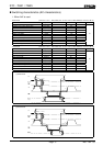
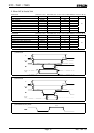
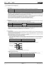
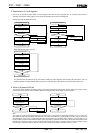
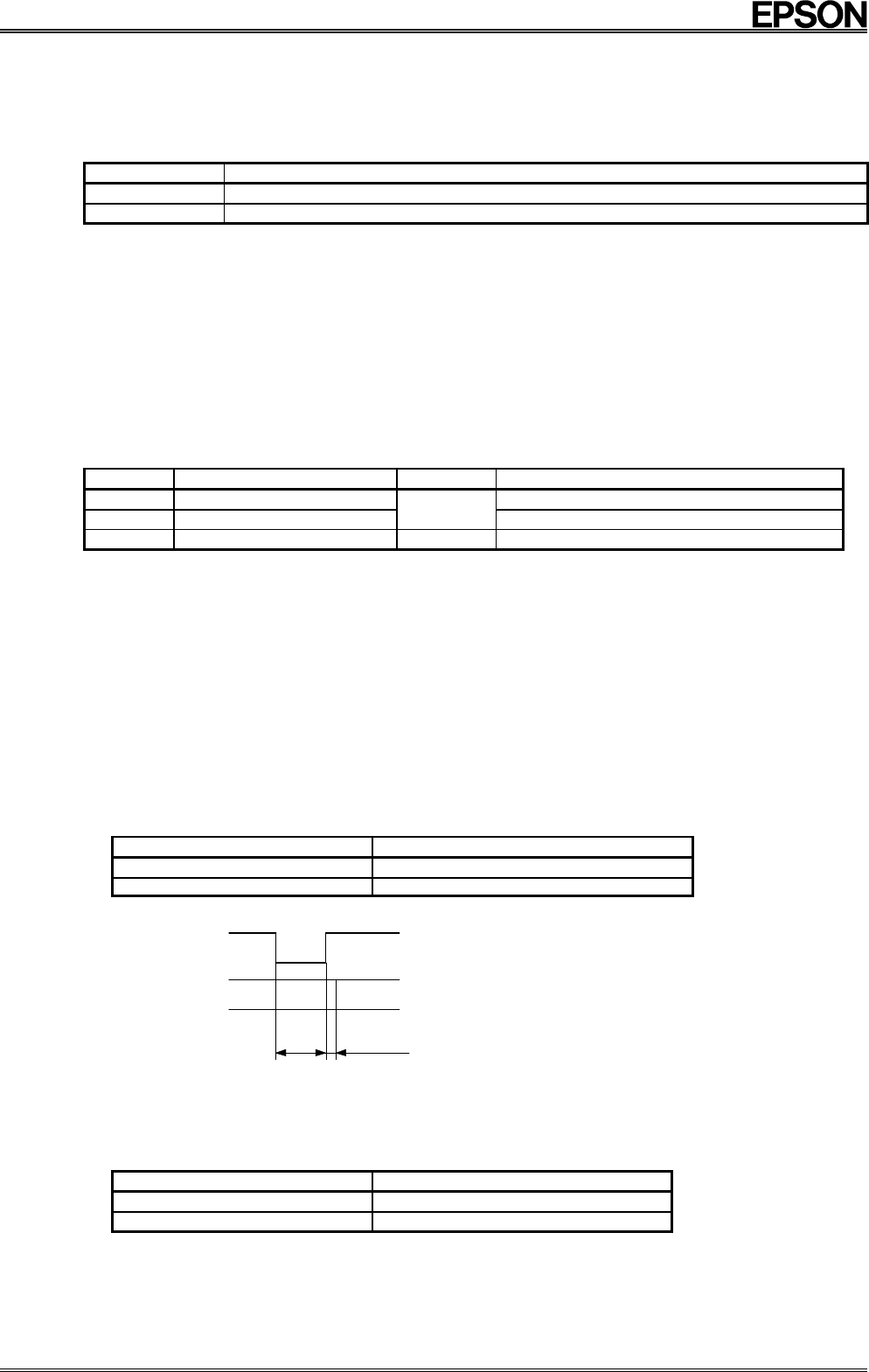
The timing of the IRQ FLAG bit and the STD.P pin output in fixed-period pulse output mode is as follows:
IRQ FLAG bit
*
STD.P pin output
01 0
7.8125 ms
Approx.
1.95 ms
The output levels of the STD.P pin are low (down) and open circuit (up).
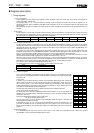
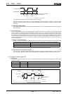
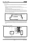
ii. STD.P pin output reset function
The STD.P pin output can be reset after an interrupt is generated by writing 0 to the IRQ FLAG bit.
The relationships of this operation are shown below. Note that writing 1 to this bit is possible, but it has no effect.
IRQ FLAG bit STD.P pin output
1 Low
0 Open(for open-drain output)