


Confidential
EPSON
TITLE
SHEET
REVISION
NO
SHEETNEXT
16 15
TM-T81
Specification
(STANDARD)
A
2.1.1.7 Notes on Resetting the Printer Using the Interface
The printer can be reset using interface pins 6 and 25 by changing the DIP switch setting. (See
Section 3.3.3, DIP switch 2.)
Table 2.1.3 Reset Switching
Signal Line DIP Switch Reset Condition
Pin 6 (DSR) DSW 2-7: ON MARK level input
Pin 25 (INIT) DSW 2-8: ON SPACE or TTL-HIGH level input
To reset the printer, the following requirements must be satisfied.
• DC characteristics:
Table 2.1.4 Reset DC Characteristics
Pin 6 (DSR) Pin 25 (INIT)
Reset active voltage VA -15 to -3 V +2 to +15 V
Reset negative voltage VN +3 to +15 V -15 to + 0.8 V
Reset active current IA -5.3 mA (maximum) 1 mA (maximum)
Reset negative current IN -5.0 mA (maximum) -2 mA (maximum)
Input impedance RIN
3 kΩ (minimum)
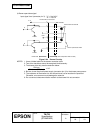
• AC characteristics:
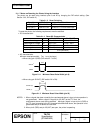
Minimum reset pulse width: T
RS 1 ms (minimum)
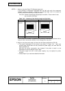
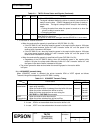
• When using pin 6 (DSR) (DIP switch 2-7 is ON):
TRS
H
L
Figure 2.1.1 Minimum Reset Pulse Width (pin 6)
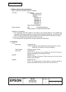
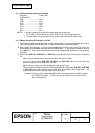
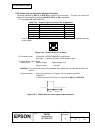
• When using pin 25 (INIT) (DIP switch 2-8 is ON):
TRS
H
L
Figure 2.1.2 Minimum Reset Pulse Width (pin 25)
NOTES: 1. When a signal that does not satisfy the requirements above is input, printer operation is
not guaranteed. When a signal is input to pin 25 (INIT) at the TTL level, the
requirements above must also be satisfied. Although a signal is input to pin 6 (DSR) at
the TTL level, according to the DC characteristics described above, the operation is not
guaranteed and pin 6 cannot be controlled.
2. When pin 6 (DSR) and pin 25 (INIT) are open, the printer is operating.
SPACE
MARK
TRS
SPACE (H)
MARK (L)
TRS