– 3 – ETAsys.com
Specifications are subject to change without notice.
1601 Jack McKay Blvd. • Ennis, Texas 75119 U.S.A.
Telephone: 800.876.3333 • Fax: 800.765.3435
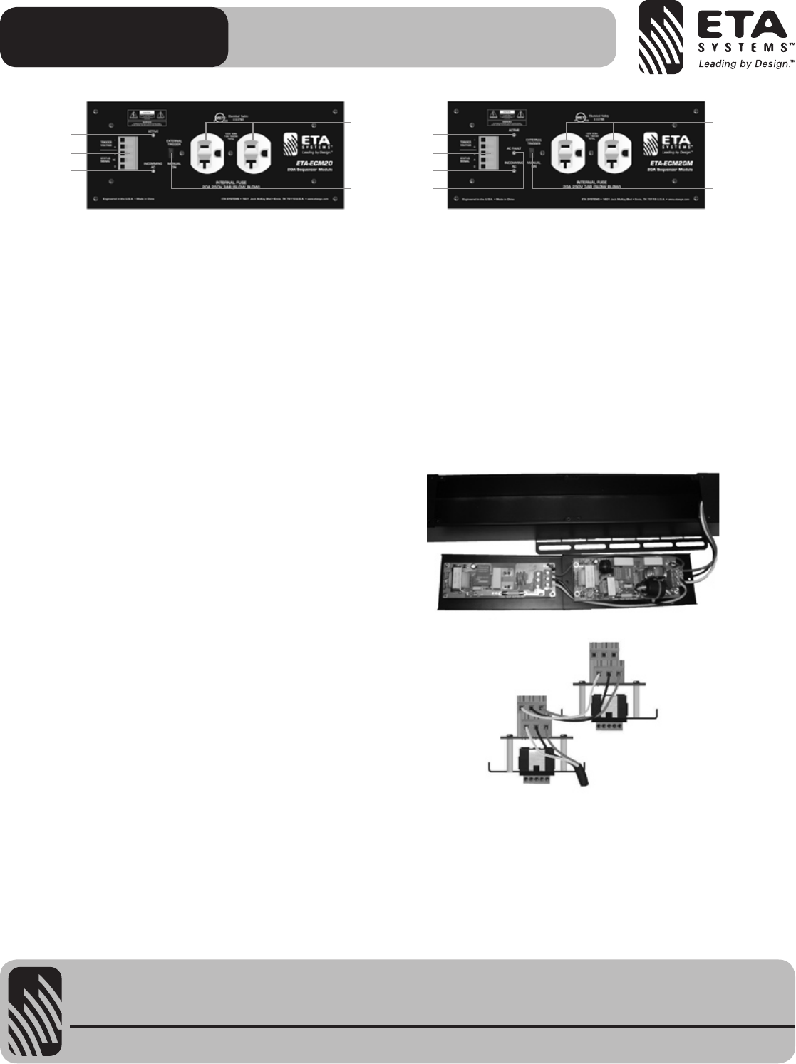
MODULE PANEL FEATURES
1. Trigger / Status Port Pin Identification – All signals are of
lowvoltageandcurrent.DONOTMISWIREordamagemay
occur.
+ Requires5-24VDCtoactivatethemodulewith5mAof
current.Note:TheDCVcanbesuppliedfromanysource.
The EVS protection requires the ETA-ECS6RM for operation.
G CircuitGround,MustbeofthesamecircuitastheDCV
source.
V AC Voltage Status Signal, this signal reports back to the
ETA-ECS6RM the Incoming AC Mains Voltage to the ECM
module.
A AC Current Status Signal, this signal reports back to the
ETA-ECS6RM the AC Mains Current draw at the ECM
module. Note: Not available on ETA-ECM20 type module.
D Fault Status Signal, reports to the ETA-ECS6RM fault
conditions of an ECM module.
2. External Trigger / Manual On Switch – The ETA-ECM20M
has a manual override switch allowing it to be used as a local
Power Conditioner and Surge Suppressor. For it to be remotely
monitored and activated the switch must be in the “External
Trigger" position.
3. Incoming AC LED – ThisLEDwillilluminateRedwhenthe
ECMhasincomingACpowerpresentatthemodule.ThisLED
mustbeOntooperate.Note:IfthisLEDisnotilluminating
check the following: 1) The unit is plugged in, 2) The AC Mains
BreakerfeedingtheAClegtotheECMmoduleisOFF,3)The
internal fuse has been damaged. This should only be inspected
by an authorized technician.
4. Active LED – ThisLEDwillilluminateGreenwhentheECM
modulehassensedtheproperDCVtotriggeractivatethe
power on circuit. Note: If connected to the ETA-ECS6RM and
theEVScircuitisactivatedthisLEDwillnotbeON.The
ChannelStatusLEDontheETA-ECS6RMwillflashindicatinga
problem and will not turn the ECM module ON until the
AC Mains voltage is stable.
5. AC Fault LED – If damage to the Spike Suppression circuit
occurredthisLEDwillilluminateRed.Themodulemaystill
operate but may not be protecting the items plugged into
theACoutlets.ThisLEDwillnotturnoffuntilrepaired.Have
the ECM module inspected by a qualified technician.
Note: Not available on ETA-ECM20 type module.
6. AC Mains Outlet – Two 120V AC 20A outlets.
WIRING THE ETA-ECM20M MODULE
The ETA-ECM20M is designed to be mated with the
ETA-RACEWY6 housing and the ETA-ECS6RM controller. The
specific job install AC power requirements and power distribution
layout will dictate how the ETA-ECM20M modules are wired into
the ETA-RACEWY6. Each ECM Module can be wired as a single
20A run or in a parallel configuration as illustrated below. Each
ECM module has dual 3-position screw terminal blocks that are in
parallel and are clearly labeled as follows:
E - Green = Ground
L-Black=Load
N - White = Neutral
Note: The above figures show the ECM wiring configuration
of one 20A AC main line coming into an ETA-ECM20M, then
paralleling with an ETA-ECM20 type module.
Note: It appears that the wiring is in series but the ECM Module
In/OutterminalsareinparallelonthePCB.
ETA-ECM20 & ETA-ECM20M
Electrical Control Module 20A Power Conditioner
3
1
4
6
2
3
5
1
4
6
2


