


– 10 – ETAsys.com
Specifications are subject to change without notice.
1601 Jack McKay Blvd. • Ennis, Texas 75119 U.S.A.
Telephone: 800-321-6699 • Fax: 800-996-3821
ETA-ECM2063
AC Power Distribution Sequencer
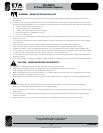
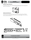
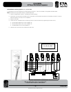
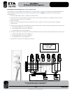
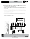
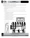
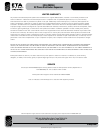
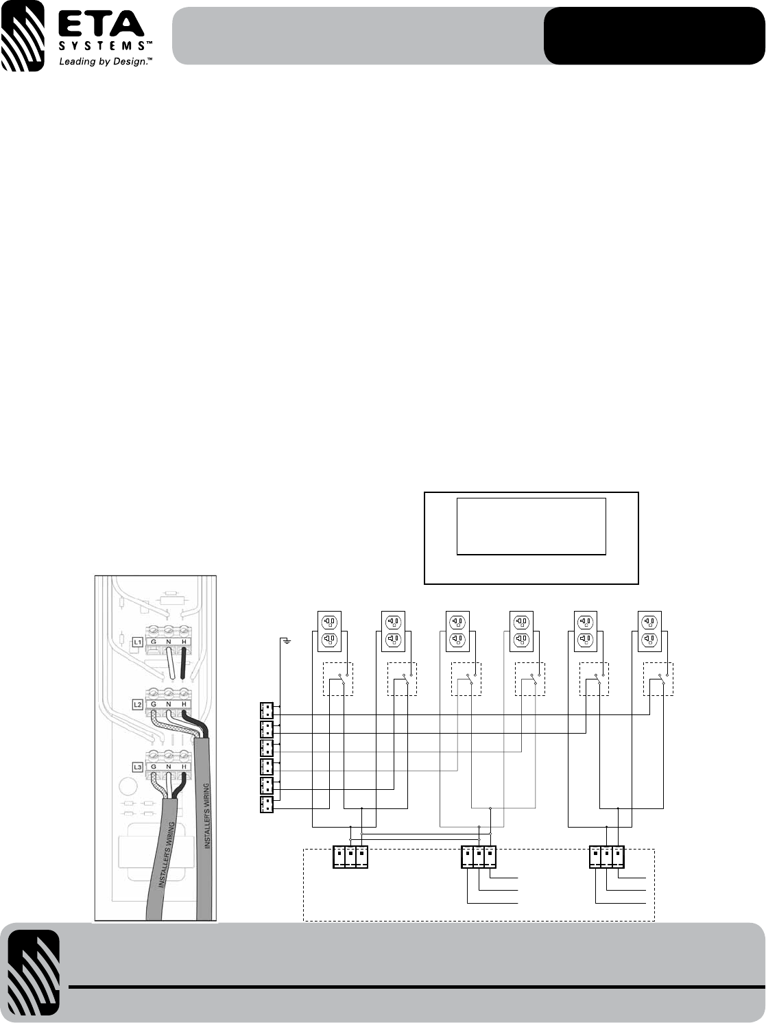
ETA-ECM2063 Load Wiring Option #2 - L1 & L2 = 20A, L3 = 20A
In this load/current wiring configuration the load sections L1 & L2 (Channels 1,2,3, & 4) are connected to a single 20A AC Mains feed
and load section L3 (Channels 5 & 6) is connected to second 20A AC Mains feed. Note: All electrical wiring must be done by a
certified electrician.
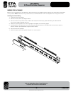
1. Followthestepslistedinsection“AccessingtheInternalWiring”
2. Choose the most convenient AC Mains inlet on the bottom of the raceway that allows for the easiest connection to the AC
Mains line based on the layout of the installation.
3. Strip the wires 3/8".
4. LocateJ23L3onthePCB.RemovethewirejumpersfromP2“N”andP3‘H”.Removewirefrompushonspadelug,
discard 2 wires.
5. L1&L2wiring:LocateJ24L2onthePCB.Insertthe20AACMainswiresintoJ24L2andsecurebytighteningthescrewsfirmly.
• Ground(GreenGRN)wireintoPin1labeled“G”
• Neutral(WhiteWHT)wireintoPin2labeled“N”
• Hot(BlackBLK)wireintoPin3labeled“H”
6. L3wiring:LocateJ23L3onthePCB.InsertthesecondACMainswiresintoJ23L3andsecurebytighteningthescrewsfirmly.
• Ground(GreenGRN)wireintoPin1labeled“G”
• Neutral(WhiteWHT)wireintoPin2labeled“N”
• Hot(BlackBLK)wireintoPin3labeled“H”
7. Leave all other wires within the chassis alone and intact.
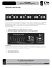
L1 & L2 = 20A
L3 = 20A
L1
CH1
G
BLK Hot
N H
CH2 CH3 CH4
CHANNEL CONTROL PORT
CH5 CH6
L2
G N H
L3
G N H
WHT Neutral
GND Green
BLK Hot
WHT Neutral
GND Green
Installer’s Wiring
CH1
K1
CH2 CH3 CH4 CH5 CH6
K2 K3
K4
K5
K6
Internal Wiring Identification Label
(To be placed on Input Plate if configured in this manner)