


PC/104-Plus – COM-1460 Module 11
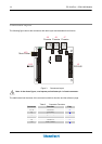
The following table provides a quick cross-reference for them.
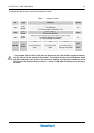
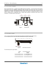
Table 1. Jumpers Function
JP Type Function Default
JP1
3 pin
jumper
Power supply for physical interface
1-2: Reserved
2-3: Power supply comes from J10
2-3
JP2
2pin
jumper
GND to GND_A
JP2 must be left open
Open
JP3
3 pin
jumper
Setting for Bus Manager Contender (BMC) state at reset
1-2: Not Bus Manager Contender
2-3: Bus Manager Contender
1-2
JP4 JP5 Slot #*
JP4-JP5
2 pin
jumper
JP4 must be left
open
JP5 must be left
open
Put COM-1460 on
the top of the stack
Open
-
Open
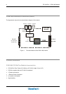
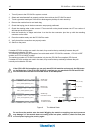
* Two jumpers (JP4 and JP5 in this case) are located on every PC/104-Plus peripheral module,
and are used to set the module’s Slot number. The module closest to the CPU Module starts
with Slot 0. Because in the stack no more than four modules are supported (in addiction to the
CPU module) the allowed values are only: 0, 1, 2 and 3. COM-1460 is normally put on the top of
the stack.