


PC/104-Plus – COM-1460 Module 15
J1, J2 for the ISA Bus and J3 for the PCI Bus
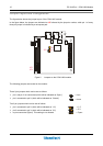
The ISA BUS
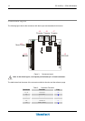
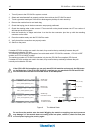
Connectors J1 and J2 carry the signals for the ISA Bus.
The ISA BUS signals are not used from the COM-1460. The only function of the ISA connector is the
“passing-through” of the signals, and giving compatibility to the stack assembly.
Below is shown a picture of the ISA BUS
J1
J2
Figure 4. ISA BUS layout
According to PC/104 specifications: “Key” locations - consisting of plugged holes in the upper side and
omitted pins in the lower side - have been designated on each bus connector (on J1 and J2), to help assure
proper connector mating.”
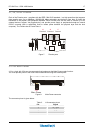
The PCI BUS
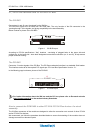
Connector J3 carries signals of the PCI Bus. The PCI Bus mechanical interface is a stackable 30x4 header.
This interface carries all of the required PCI signals per PCI Local Bus Specification Version. 2.1.
In the following page is shown a picture of the PCI BUS
J3
PCI BUS
Figure 5. PCI BUS layout
For further information about the ISA bus and the PCI bus please refer to Eurotech web site
(http://www.eurotech.it/
) in the section Industry Standards.
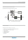
How to connect the COM-1460 to other PC/104 & PC/104-Plus devices: the stack
assembly
The ISA Bus connectors of the module are designed to allow the connection onto a stack of other PC/104
and/or PC/104-Plus devices.
We recommend you follow the procedure described below to ensure that stacking of the modules does not
damage connectors or electronic parts.