


Hardware Installation
17
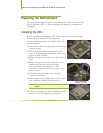
4. Ensure that the fan assembly is aligned with the chassis vents according to
the fan assembly instruction.
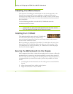
5. Secure the motherboard with a minimum of eight-to-ten screws.
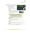
Connecting Cables and
Setting Switches
This section takes you through all the connections and switch settings necessary
on the motherboard. This will include:
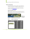
Power Connections
¾ 24-pin ATX power (
PWR1)
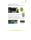
¾ 8-pin ATX 12V power (
PWR2)
¾ Auxiliary power for graphics (
PWR3)
Internal Headers
¾ Front panel
¾ IEEE 1394a
¾ USB Headers
¾ Audio
¾ Speaker
¾ COM
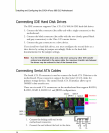
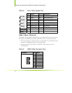
FDD
IDE
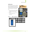
Serial ATA II
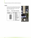
Chassis Fans
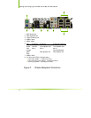
Rear panel USB 2.0 Adapter
Expansion slots
CMOS jumper settings
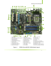
See Figure 1 on page 11 to locate the connectors and jumpers referenced in the
following procedure.