


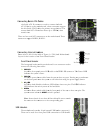
Audio
The audio connector supports the HD audio standard. Most cases come with a 10 pin
standard block which will align and plug directly in to the header. In some cases there will
be individual plugs which will need to be plugged in.
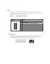
Table 1. Front Audio Connector
Connector Pin Signal
Front Audio Connector
1 PORT1_L - Analog Port 1 - left channel (Microphone)
2 AUD_GND - Ground
3 PORT1_R – Analog Port 1 – right channel (Microphone)
4 PRESENCE# - Active signal that indicates FP audio is present
5 PORT2_R – Analog Port 2 - right channel (Headphone)
6 SENSE1_RETURN – Jack detection return for front panel (Jack1)
7 SENSE_SEND – Jack detection sense line
8 Empty
9 PORT2_L – Analog port 2 – left channel (Headphone)
10 SENSE2_RETURN – Jack detection return for front panel (Jack2)
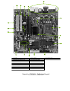
Fan Connections
There are two types fan connections, the system fan and the CPU fan. The fan speed can be
detected and viewed in the
PC Health Status section of the CMOS Setup. Both fans are
automatically turned off after the system enters S3, S4 and S5 mode.
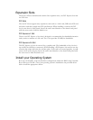
2
4
6
8
10
1
3
5
7
9
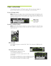
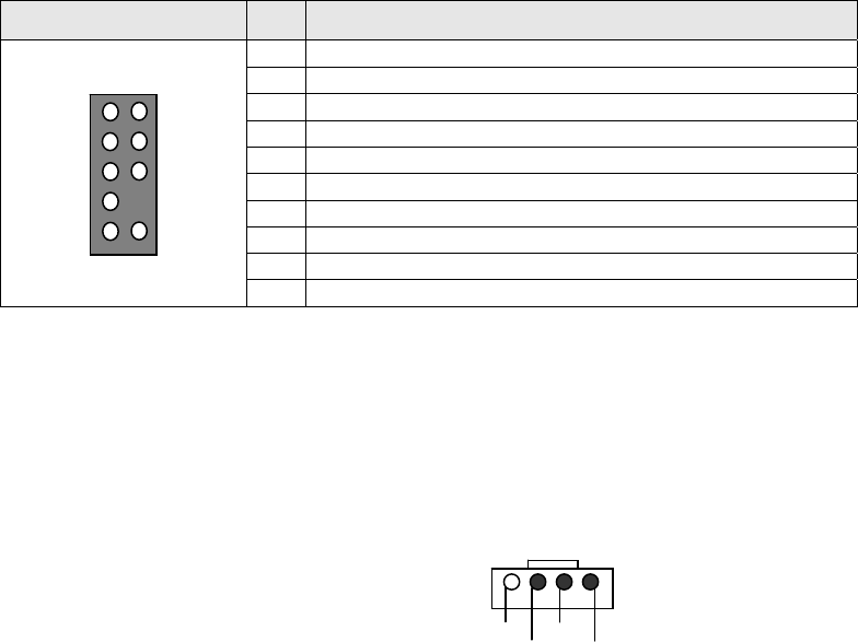
Note that the CPU fan cable can be
either a 3-pin or a 4-pin connector.
Connect a 3-pin connector to pins 1, 2,
and 3 on the motherboard connector.
CPU Fan Connector
4 3 2 1
GND SENSE
PWR CONTROL